Application of Type 409 1.1 kV–22 kV Mining Cable in Continuous Miners & Longwall Shearers: A Comprehensive Technical Guide
Discover how Type 409 mining cables power continuous miners and longwall shearers in Australian coal mines. Learn about electrical parameters, installation standards, and real-world applications with detailed technical specifications.
6/12/202523 min read
Application of Type 409 1.1 kV–22 kV Mining Cable in Continuous Miners & Longwall Shearers: A Comprehensive Technical Guide
1. Introduction
1.1 Context & Significance
Underground coal mining operations in Australia represent some of the most demanding electrical environments on Earth. Deep beneath the surface, where temperatures soar, humidity levels fluctuate dramatically, and mechanical stresses push equipment to breaking point, reliable power delivery becomes absolutely critical. Every piece of machinery operating in these harsh conditions depends on robust electrical infrastructure that can withstand the unique challenges of subterranean mining operations.
The importance of mining cables cannot be overstated when considering the safety and productivity of modern coal extraction. A single cable failure can halt production across an entire mine section, potentially costing operators hundreds of thousands of dollars per hour in lost revenue. More critically, electrical failures in underground environments can create serious safety hazards, from fire risks to the potential for explosive gas ignition in coal seams that produce methane.
Type 409 series cables have emerged as a cornerstone solution for powering heavy mining machinery in Australian operations. These specialized cables bridge the gap between surface electrical infrastructure and the demanding requirements of underground continuous miners and longwall shearers. Their design philosophy centers on delivering maximum reliability while maintaining the flexibility necessary for dynamic mining operations.
1.2 Scope of the Article
This comprehensive technical guide focuses specifically on the application of Type 409 cables in powering two critical pieces of mining equipment: continuous miners (often called "cutters" in Australian mining parlance) and longwall shearers. These machines represent the cutting edge of coal extraction technology, literally and figuratively, as they mechanically remove coal from active mine faces.
Throughout this analysis, we'll examine how Type 409 cables meet the unique electrical demands of these machines, explore their construction features that enable reliable operation in challenging mining environments, and provide practical guidance for installation and maintenance. The discussion includes real-world applications drawn from Australian mining operations, where these cables have proven their worth in some of the world's most productive coal mines.
2. Overview of Mining Machines: Cutters & Shearers
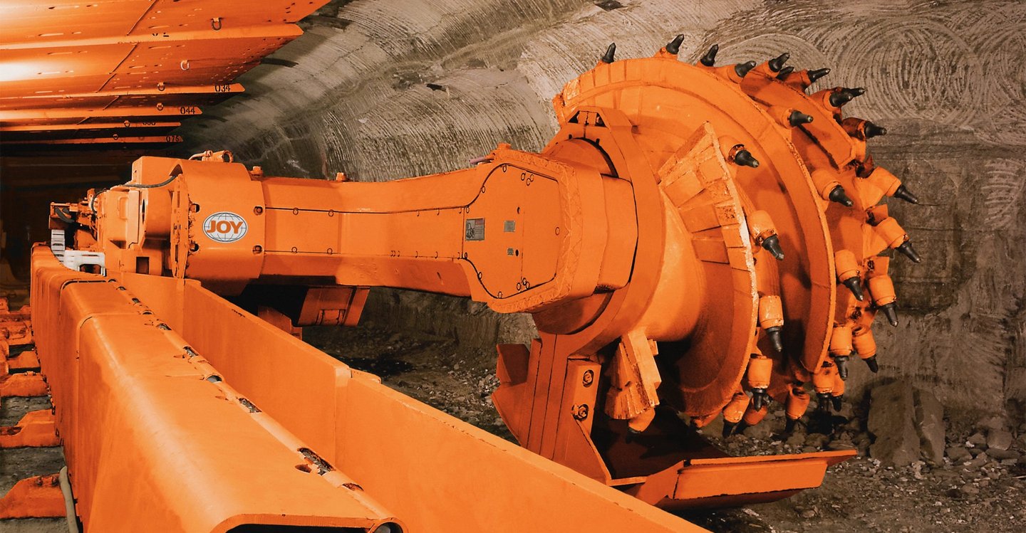
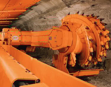
2.1 Continuous Miner (Cutter)
The continuous miner, affectionately known as a "cutter" throughout Australian coal mines, represents a marvel of modern mining engineering. This massive machine combines the functions of coal cutting, loading, and conveying into a single integrated unit that can extract coal continuously from a mine face. Picture a mechanical beast weighing upwards of 100 tonnes, equipped with a rotating cutting head studded with carbide-tipped picks that can chew through coal seams with remarkable efficiency.
The power demands of a continuous miner are substantial and highly variable. During active cutting operations, these machines typically draw between 500 to 1500 kilowatts of electrical power, depending on coal hardness, seam thickness, and cutting speed. The electrical load profile presents unique challenges because power consumption fluctuates dramatically as the cutting head encounters different coal conditions or rock bands within the seam.
Most Australian continuous miners operate at medium voltage levels, typically 3.3 kV or 6.6 kV, though some larger operations utilize 11 kV systems for improved efficiency over long cable runs. The machines require not only high-power supply for their cutting and tramming motors but also lower-voltage control circuits for hydraulic systems, lighting, and sophisticated monitoring equipment that tracks cutting performance and detects potential hazards.
The dynamic nature of continuous miner operations creates particular challenges for power supply cables. Unlike stationary equipment, cutters constantly move forward as they advance through coal seams, requiring their power cables to be "trailed" behind them rather than permanently installed. This trailing configuration subjects cables to continuous flexing, dragging across rough mine floors, and occasional impact from falling coal or rock.
2.2 Longwall Shearer
Longwall mining represents the pinnacle of high-production coal extraction, and the shearer serves as the heart of this sophisticated system. Australian longwall operations routinely produce over 10,000 tonnes of coal per day, with the shearer methodically traveling back and forth across coal faces that can extend 300 metres or more in width.
The longwall shearer differs significantly from continuous miners in its operating pattern and power requirements. Rather than the intermittent cutting action of a continuous miner, shearers perform reciprocating slice cuts across the entire longwall face. This creates a more consistent power demand profile, though peak power requirements can exceed 2000 kilowatts during heavy cutting conditions.
Electrical loading characteristics of longwall shearers present unique challenges due to their continuous reciprocating motion along the longwall face. The shearer travels on a rigid conveyor system called an Armoured Face Conveyor (AFC), with power supplied through a combination of trailing cables and specialized cable handling systems. The electrical supply must accommodate not only the high-power cutting motors but also sophisticated automation systems that control cutting height, advance speed, and coal loading efficiency.
Compared to continuous miners, longwall shearers operate in a more controlled environment regarding cable management. The shearer's movement follows a predictable path along the longwall face, allowing for more sophisticated cable handling systems. However, the higher production rates and longer operating cycles place greater demands on cable reliability, as any failure can shut down the entire longwall system.
The power supply requirements for longwall shearers typically involve higher voltages than continuous miners, often 11 kV or even 22 kV for the largest operations. This higher voltage selection reduces current levels for the same power transmission, allowing for smaller conductor sizes and reduced cable weight—critical considerations when cables must be handled and repositioned multiple times per shift.
3. Electrical Requirements & Parameters
3.1 Voltage & Power Ratings
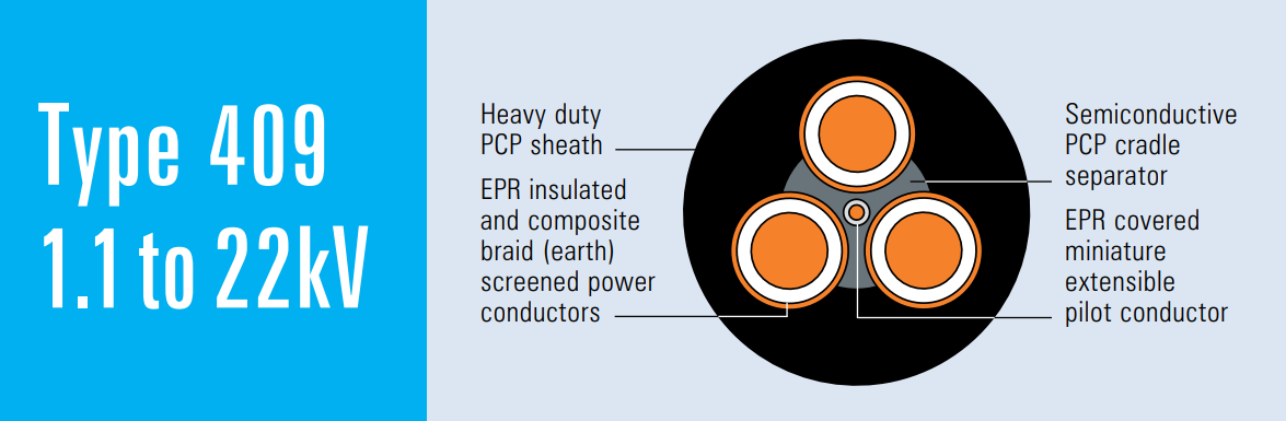
Understanding the voltage and power requirements for mining machinery requires appreciating the complex relationship between electrical efficiency, safety requirements, and practical installation constraints in underground environments. The Type 409 cable series accommodates voltage ranges from 1.1 kV up to 22 kV, providing flexibility to match various mining applications and operational requirements.
The selection of operating voltage for mining equipment involves balancing multiple factors. Higher voltages allow for reduced current levels at equivalent power levels, which translates to smaller conductor cross-sections and lighter cables. This weight reduction becomes critically important when considering that mining cables must often be manually handled during installation and repositioning operations. However, higher voltages also introduce additional safety considerations and require more sophisticated insulation and protection systems.
Machine size directly influences voltage selection in Australian mining operations. Smaller continuous miners operating in development headings might utilize 1.1 kV or 3.3 kV systems, while large production longwall shearers typically operate at 11 kV or 22 kV. The relationship between machine size and voltage selection also considers the distance from surface electrical infrastructure, as higher voltages reduce transmission losses over long cable runs that can extend several kilometers underground.
Duty cycle considerations play a crucial role in determining appropriate voltage and power ratings. Continuous miners often operate intermittently, with cutting cycles interspersed with tramming and positioning operations. This intermittent duty allows for higher short-term power levels but requires cables that can handle dynamic loading conditions. Longwall shearers, conversely, operate in more continuous duty cycles but with more predictable loading patterns.
3.2 Cable Capacity & Conductor Sizing
The conductor sizing for Type 409 cables reflects careful engineering to match the diverse power requirements of mining machinery while maintaining practical handling characteristics. Available conductor cross-sections range from 6 mm² for smaller applications up to 300 mm² for the most demanding high-power installations.
Current carrying capacity calculations for mining cables must account for unique operating conditions that differ significantly from standard industrial applications. Underground mining environments often feature elevated ambient temperatures, particularly in deeper mines where geothermal heating becomes significant. Additionally, cables may be bundled together or installed in confined spaces that limit heat dissipation, requiring derating of nominal current capacities.
The effect of continuous versus dynamic operation on conductor sizing presents interesting engineering challenges. While longwall shearers typically operate in steady-state conditions that allow full utilization of cable current ratings, continuous miners subject cables to dynamic loading that can include starting surges, stall conditions, and rapid load changes. These dynamic conditions require conservative sizing approaches to ensure cables can handle peak demands without overheating.
Conductor strand configuration also influences current capacity and mechanical properties. The Type 409 series utilizes fine-strand construction with tinned copper conductors that provide excellent flexibility while maintaining low electrical resistance. The tinning process enhances corrosion resistance in humid mining environments and improves long-term reliability.
3.3 Insulation & Shielding Characteristics
Ethylene Propylene Rubber (EPR) insulation forms the backbone of Type 409 cable reliability in demanding mining environments. EPR offers exceptional performance characteristics that make it particularly well-suited for mining applications, including excellent flexibility at low temperatures, resistance to moisture absorption, and superior aging characteristics under thermal stress.
The performance advantages of EPR insulation become particularly evident when comparing operational requirements in mining environments. Unlike standard PVC insulation that becomes brittle at low temperatures, EPR maintains flexibility across a wide temperature range, from the chill of surface winter conditions to the heat of deep underground operations. This temperature stability ensures consistent electrical performance and mechanical durability throughout varied operating conditions.
Semiconductor screens play a critical role in maintaining electrical integrity, particularly for cables rated at 3.3 kV and above. The conductor screen provides a smooth, uniform electric field interface between the conductor and insulation, preventing voltage concentrations that could lead to insulation breakdown. The insulation screen serves a similar function on the outer insulation surface, ensuring uniform voltage distribution and providing a pathway for fault currents.
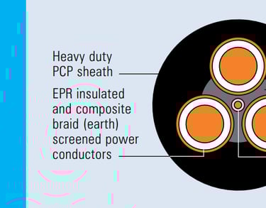
The composite earth screen represents a sophisticated approach to fault protection and electromagnetic compatibility. This screen combines tinned copper braiding with polyester yarn reinforcement, creating a robust return path for fault currents while providing mechanical protection for inner cable components. The braided construction maintains flexibility while offering excellent fault current handling capability, essential for rapid fault detection and clearance in mining environments.
3.4 Thermal and Mechanical Ratings
Maximum operating temperature ratings for Type 409 cables reflect the demanding thermal environment of underground mining operations. EPR insulation can typically handle continuous operating temperatures up to 90°C, with emergency overload capability to higher temperatures for short durations. This thermal capacity provides adequate safety margins for most mining applications while allowing for elevated ambient temperatures in deep mines.
Flexibility and bending radius specifications become critical factors when considering the dynamic nature of mining cable applications. Type 409 cables are designed with minimum bending radius typically specified as 15 times the overall cable diameter, though this can vary based on specific construction details and operating conditions. This flexibility allows cables to be trailed behind moving machinery without suffering mechanical damage.
The mechanical durability requirements for mining cables extend beyond simple flexibility to include resistance to abrasion, impact, and crushing forces. Mining environments subject cables to harsh mechanical treatment, from being dragged across rough rock surfaces to potential impact from falling materials. The heavy-duty PCP (Polychloroprene) sheath provides excellent resistance to these mechanical stresses while maintaining flexibility.


4. Type 409 Cable Construction
4.1 Conductor
The conductor design philosophy for Type 409 cables centers on achieving optimal balance between electrical performance, mechanical flexibility, and long-term reliability in harsh mining environments. Flexible stranded tinned annealed copper conductors form the foundation of this design approach, with each element carefully selected to contribute to overall cable performance.
Tinned copper construction provides several advantages over bare copper in mining applications. The tin coating acts as a barrier against corrosion from moisture and chemical contaminants commonly found in mining environments. This corrosion protection becomes particularly important in coal mines where acidic conditions can develop from sulfur-bearing minerals or where chemical cleaning agents are used for dust suppression.
The annealing process ensures maximum conductor flexibility by removing work-hardening that occurs during wire drawing operations. This soft copper construction allows for repeated flexing without fatigue, essential for cables that must trail behind moving machinery. The fine stranding pattern, typically utilizing hundreds of individual wire strands, further enhances flexibility while maintaining excellent electrical conductivity.
Conductor sizing across the Type 409 range accommodates diverse power requirements from small hand-held tools to massive longwall shearers. The progression from 6 mm² to 300 mm² conductor cross-sections allows precise matching of cable capacity to equipment requirements, avoiding both undersized cables that might fail under load and oversized cables that create unnecessary weight and cost burdens.
4.2 Insulation & Screens
EPR insulation represents a mature technology that has proven itself through decades of successful application in demanding environments. The cross-linked molecular structure of EPR provides excellent resistance to thermal aging, moisture absorption, and chemical attack while maintaining flexibility across a wide temperature range.
The insulation thickness varies according to voltage rating, with careful attention to providing adequate dielectric strength while minimizing overall cable diameter and weight. For example, cables rated at 6.6 kV typically feature insulation thickness around 5.0 mm, while 22 kV rated cables require substantially thicker insulation to maintain the same level of electrical safety.
Conductor screens serve a critical function in cables rated 3.3 kV and above by managing electric field distribution around the conductor surface. Without this semiconductive interface, irregularities in conductor surface or insulation interface could create localized high electric field concentrations that might lead to partial discharge and eventual insulation failure. The semiconductive compound provides a smooth electrical transition that eliminates these stress concentrations.
Insulation screens perform a complementary function on the outer insulation surface, ensuring uniform electric field distribution and providing a defined ground reference point. This screen also facilitates fault detection by providing a low-impedance path for fault currents, enabling protective relaying systems to rapidly detect and clear ground faults that could pose safety hazards in mining environments.
4.3 Earth / Composite Screen
The composite earth screen design represents an innovative approach to combining fault protection with mechanical durability requirements. Traditional mining cables often utilize simple copper tape or wire screens that can suffer mechanical damage during installation or operation. The Type 409 composite screen integrates tinned copper braiding with polyester yarn reinforcement to create a robust yet flexible earth return path.
Copper braiding provides excellent electrical conductivity for fault current return while maintaining flexibility for dynamic applications. The braided construction distributes mechanical stresses across multiple conductors, reducing the likelihood of fatigue failure compared to solid tape constructions. Tinning the copper braid enhances corrosion resistance and ensures long-term electrical integrity.
Polyester yarn interwoven with the copper braid adds significant mechanical strength and abrasion resistance. This reinforcement allows the composite screen to withstand the harsh mechanical treatment typical of mining environments while maintaining electrical continuity. The polyester component also provides additional moisture resistance and chemical stability.
The fault current return path function of the composite screen enables rapid fault detection and clearance, essential for mining safety. Ground fault protection systems rely on the screen to provide a low-impedance path for fault currents, allowing protective relays to detect dangerous ground faults and disconnect power before hazardous conditions develop.
4.4 Central Extensible Pilot
The central extensible pilot conductor serves multiple functions that extend far beyond simple control signal transmission. In modern mining operations, this pilot conductor often carries critical safety and monitoring signals that enable sophisticated equipment protection and performance optimization systems.
EPR covering on the pilot conductor provides the same excellent environmental resistance as the main power conductors, ensuring reliable signal transmission even under challenging conditions. The pilot conductor must maintain signal integrity while withstanding the same mechanical stresses as the main cable, requiring robust construction that balances flexibility with durability.
Extensible design features allow the pilot conductor to accommodate the dynamic length changes that occur as trailing cables are extended and retracted during mining operations. Without this extensibility, the pilot conductor could suffer mechanical stress or failure as the main cable length changes, potentially disrupting critical control and monitoring functions.
Control and communication signal applications for the pilot conductor continue to expand as mining equipment becomes more sophisticated. Modern systems may transmit data regarding cutting performance, equipment health monitoring, environmental conditions, and safety system status through the pilot conductors, making their reliable operation essential for modern mining operations.
4.5 Sheath Types
Heavy-duty PCP (Polychloroprene) sheath provides the primary protection against the harsh mechanical and environmental conditions encountered in mining applications. PCP offers excellent resistance to abrasion, tearing, and impact damage while maintaining flexibility across a wide temperature range. The material also provides good resistance to oils, greases, and cleaning chemicals commonly used in mining environments.
Standard PCP sheath construction represents the optimal balance of performance and cost for most mining applications. The sheath thickness is carefully engineered to provide adequate mechanical protection without excessive weight or stiffness that could compromise cable handling characteristics. Typical sheath thickness ranges from 3.8 mm for smaller cables to over 10 mm for the largest conductor sizes.
Alternative sheath options including CPE (Chlorinated Polyethylene) and CSP (Chlorosulfonated Polyethylene) are available for specialized applications requiring enhanced chemical resistance or specific environmental performance characteristics. These materials may be specified for applications involving exposure to specific chemicals or extreme environmental conditions not adequately addressed by standard PCP construction.
The sheath selection process should consider the specific environmental conditions and mechanical stresses expected in each application. While PCP provides excellent general-purpose performance, specialized environments may benefit from alternative sheath materials that offer enhanced resistance to specific chemicals, temperature extremes, or mechanical stresses.
4.6 Dimensional Range
The comprehensive dimensional range of Type 409 cables reflects careful attention to matching cable characteristics with specific application requirements. Overall diameter progression from approximately 30 mm for the smallest cables to over 109 mm for the largest sizes provides options for diverse power requirements while maintaining reasonable handling characteristics.
Weight considerations become increasingly important for larger cable sizes, particularly in applications requiring frequent cable handling or repositioning. The weight progression from 129 kg/100m for small cables to over 2120 kg/100m for the largest sizes requires careful consideration of material handling equipment and installation procedures.
Conductor cross-sectional area progression follows standard metric sizing to facilitate electrical calculations and equipment selection. The range from 6 mm² to 300 mm² accommodates current requirements from small auxiliary equipment to the largest mining machinery while providing intermediate sizes for precise application matching.
Sheath thickness scaling with cable size ensures adequate mechanical protection across the entire size range while maintaining proportional flexibility characteristics. The engineering challenge involves providing sufficient mechanical protection for larger cables without creating excessively stiff constructions that would be difficult to handle or install.
5. Applications & Suitability
5.1 Mechanical Deployment
The trailing power feed application represents the primary use case for Type 409 cables in continuous miner and longwall operations. Unlike reeling cables that are wound and unwound from drums, trailing cables are simply dragged behind moving equipment, creating unique mechanical stress patterns and operational requirements.
Continuous miner trailing applications present particular challenges due to the irregular movement patterns of these machines. As a cutter advances through a coal seam, it may need to maneuver around obstacles, retreat for maintenance, or change direction to follow optimal coal conditions. This irregular movement pattern subjects trailing cables to complex mechanical stresses including bending, twisting, and abrasion against mine surfaces.
Cable handling equipment for trailing applications ranges from simple cable hooks and guides to sophisticated automated systems that manage cable positioning and prevent excessive stress concentrations. Proper cable handling becomes critical for achieving acceptable service life, as improper handling can quickly damage even the most robust cable construction.
Longwall shearer applications typically involve more sophisticated cable handling systems due to the higher power levels and more predictable movement patterns. Specialized cable hangers, guides, and tensioning systems help manage the large, heavy cables required for longwall operations while preventing damage from the continuous reciprocating motion of the shearer.
5.2 Comparison to Other Cables
The advantages of Type 409 trailing cables over reeling cable systems become apparent when considering the operational requirements of modern mining machinery. Reeling cables must be wound and unwound from drums, limiting their flexibility and requiring more complex mechanical systems for cable management. Trailing cables eliminate these mechanical complications while providing superior flexibility for dynamic applications.
Flexibility advantages of Type 409 construction allow these cables to follow the irregular paths required by mining machinery without suffering mechanical damage. The fine-strand conductor construction and EPR insulation system provide exceptional flexibility that cannot be matched by more rigid cable constructions designed for stationary installations.
Robustness characteristics of Type 409 cables reflect their specialized design for mining environments. The heavy-duty sheath construction, composite earth screen, and overall mechanical design provide superior resistance to the mechanical abuse typical of mining operations compared to standard industrial cables.
Matching cable specifications to specific machinery loads requires careful consideration of both electrical and mechanical requirements. While electrical calculations might suggest a particular conductor size, mechanical requirements for flexibility, weight, and durability might dictate different sizing approaches. The broad range of Type 409 configurations allows optimization for specific applications rather than forcing compromises with limited options.
6. FAQ: Potential Mining Challenges & Solutions
6.1 What is the recommended bending radius for Type 409 cables?
The recommended minimum bending radius for Type 409 cables follows the general industry guideline of 15 times the overall cable diameter, though specific applications may require more conservative approaches. This specification ensures that internal cable components do not suffer excessive mechanical stress during installation or operation. For example, a cable with 60 mm overall diameter should not be bent to a radius less than 900 mm during installation or normal operation.
The bending radius becomes particularly critical during cable installation and routing around obstacles in mining environments. Sharp bends can damage internal components, create stress concentrations that lead to premature failure, or compromise the integrity of the composite earth screen. Proper cable routing design should anticipate bending requirements and provide adequate space for gentle curves rather than sharp direction changes.
Dynamic bending applications, such as trailing behind moving equipment, may require more conservative bending radius limits to account for fatigue effects. Repeated flexing in the same location can cause gradual degradation of cable components even if individual bending cycles remain within acceptable limits. Mining operators should monitor cables for signs of fatigue in high-flex areas and implement preventive replacement programs.
6.2 How can operators inspect for internal insulation degradation?
Periodic electrical testing provides the most reliable method for detecting insulation degradation before it leads to cable failure. DC hipot testing applies controlled high voltage to measure insulation resistance and detect deterioration that might not be visible externally. This testing should be performed according to established schedules based on cable age, operating conditions, and manufacturer recommendations.
Tan delta testing, also known as insulation dissipation factor measurement, provides more sensitive detection of insulation condition changes. This test measures the phase angle between applied voltage and resulting current, with increasing values indicating insulation degradation. While more sophisticated than simple insulation resistance testing, tan delta measurements can detect problems at earlier stages when corrective action may prevent failure.
Visual inspection of cable sheath condition provides important supplementary information about overall cable health. Look for signs of mechanical damage, abrasion, cuts, or chemical attack that might compromise sheath integrity and allow moisture ingress. Any visible damage should prompt immediate electrical testing to verify that internal components remain unaffected.
Temperature monitoring during operation can reveal developing problems through abnormal heating patterns. Thermographic inspection of energized cables may detect hot spots indicating loose connections, internal damage, or overloading conditions. Regular thermal surveys provide trending information that can predict problems before they cause failures.
6.3 How can moisture ingress be prevented?
Maintaining sheath integrity represents the primary defense against moisture ingress in mining cable applications. Regular inspection for cuts, abrasion, or puncture damage should be followed by immediate repair using appropriate techniques and materials. Even small sheath defects can allow moisture entry that gradually degrades insulation and earth screen components.
Proper end-sealing using appropriate glands and termination techniques prevents moisture entry at cable terminations. Mining environments often feature high humidity or direct water exposure from dust suppression systems, making effective sealing critical. Cable glands should be selected for mining duty and installed according to manufacturer specifications to ensure long-term sealing effectiveness.
Cable routing and support systems should minimize water accumulation around cables while providing adequate drainage for areas where water exposure cannot be avoided. Avoid routing cables through low areas where water might pool, and provide adequate support to prevent cable sagging that could create water traps.
Regular inspection schedules should include specific attention to areas where moisture ingress is most likely, such as terminations, areas of mechanical damage, or locations where cables pass through wet areas. Early detection and remediation of moisture problems can prevent major failures and extend cable service life.
6.4 What measures address abrasion at entry points?
Protective sleeves or abrasion-resistant conduit at cable entry points provide mechanical protection in areas of frequent contact or movement. These protective measures should be selected based on the specific abrasion mechanism and severity expected in each application. Heavy-duty rubber sleeves may suffice for light contact, while steel conduit might be required for severe abrasion conditions.
Entry point design should minimize sharp edges or rough surfaces that could damage cable sheaths during installation or normal operation. Smooth, rounded entry openings reduce abrasion potential and extend cable service life. Consider using bushings or grommets to provide smooth cable transitions through openings in equipment panels or structural components.
Cable routing strategies should avoid areas of high mechanical stress where possible, using alternative paths that reduce exposure to abrasive conditions. When abrasive conditions cannot be avoided, implement regular inspection and rotation schedules to distribute wear across different cable sections rather than allowing concentrated damage in single locations.
Maintenance programs should include regular inspection of high-wear areas with prompt replacement or repositioning of cables showing significant abrasion damage. Establishing wear limits and replacement criteria helps prevent abrasion-related failures while optimizing cable utilization and replacement costs.
6.5 Can Type 409 cables handle repeated flexing?
The structural design of Type 409 cables specifically addresses the repeated flexing requirements of mining applications through several key features. Fine-strand tinned copper conductors provide excellent flexibility while resisting fatigue failure under repeated bending cycles. The strand configuration distributes mechanical stresses across many individual wires rather than concentrating stress in few large conductors.
EPR insulation maintains flexibility across wide temperature ranges while resisting degradation from repeated flexing. Unlike thermoplastic insulation materials that may crack or fail under repeated bending, EPR's elastomeric properties allow it to return to original shape after each flex cycle without accumulating damage.
The composite earth screen design balances electrical performance with mechanical durability requirements for dynamic applications. The braided construction distributes stresses across multiple conductors while the polyester reinforcement provides additional mechanical strength and abrasion resistance during flexing operations.
Monitoring recommendations for high-flex applications include regular inspection of cables in areas subject to repeated bending, with particular attention to stress concentration points where flexing patterns may create localized wear. Establishing replacement criteria based on visible wear or electrical testing results helps prevent flex-related failures while optimizing cable utilization.
6.6 How are voltage and fault protection issues addressed?
The composite earth screen and pilot conductor design of Type 409 cables enables rapid fault detection and protection system operation. The low-impedance earth return path provided by the composite screen ensures that ground faults produce sufficient current flow to operate protective relaying systems quickly, minimizing arc duration and reducing fire or explosion risks.
Earth-leakage or ground-fault relay installation provides sensitive protection against dangerous ground faults that might not produce sufficient current to operate conventional overcurrent protection. These specialized relays detect small imbalances between phase and earth currents, indicating insulation failure or accidental grounding that could create shock hazards or ignition sources.
Voltage protection systems should coordinate with cable ratings and installation characteristics to provide appropriate protection without nuisance tripping. Consider both steady-state voltage ratings and temporary overvoltage capability when setting protection parameters, particularly for applications involving motor starting or other transient conditions.
Regular testing of protection systems ensures continued effectiveness and proper coordination with cable characteristics. Protection system testing should verify both pickup accuracy and operating speed to ensure rapid fault clearance while avoiding unnecessary shutdowns from transient conditions.
6.7 What happens if the pilot conductor fails?
Loss of control signals from pilot conductor failure can disrupt equipment operation and safety systems, potentially requiring immediate shutdown until repairs can be completed. Modern mining equipment relies heavily on control and monitoring signals transmitted through pilot conductors, making their reliable operation critical for safe and efficient operations.
Dual pilot conductor installation or redundant control wiring systems provide backup communication paths that allow continued operation even if one pilot conductor fails. This redundancy approach requires careful system design to ensure that backup systems can handle all critical control and safety functions without compromising operational safety.
Alternative communication methods, such as wireless systems or fiber optic links, might provide backup communication capability for critical functions. However, these alternatives must be carefully evaluated for reliability and safety in mining environments where electromagnetic interference or physical damage could affect wireless systems.
Emergency shutdown procedures should be established for situations where pilot conductor failure compromises safety system operation. Equipment operators must understand which functions are affected by pilot conductor failure and when continued operation becomes unsafe.
6.8 How do Type 409 cables integrate with longwall shield systems?
Longwall shield system compatibility requires careful attention to cable support and strain relief systems that accommodate the complex movements of both shearers and individual shield units. The shields must advance periodically to maintain support of the mine roof as coal is extracted, creating dynamic loading conditions for power supply cables.
Strain relief systems typically include specialized cable hangers or support tracks that distribute cable weight and prevent excessive stress concentrations at connection points. These systems must accommodate both the reciprocating motion of the shearer along the longwall face and the periodic advance of the shield line.
Sheathed canopy guidance systems provide protection for cables in areas where they might be exposed to falling materials or mechanical damage from shield operations. These protective systems must balance cable protection with accessibility for maintenance and the need to accommodate dynamic shield movements.
Integration considerations should address both normal operating conditions and emergency situations where rapid shield advance or equipment removal might be required. Cable routing and support systems must provide adequate accessibility for emergency operations while maintaining protection during normal operations.
6.9 What are the maximum temperature considerations in hot seams?
EPR insulation and PCP sheath materials typically provide reliable operation up to 90°C continuous operating temperature, with short-term emergency overload capability to higher temperatures. This thermal rating provides adequate safety margin for most mining applications while accommodating elevated ambient temperatures in deep mines or areas with high geothermal gradients.
Temperature monitoring becomes critical in applications approaching thermal limits, requiring regular measurement of both ambient conditions and cable operating temperatures. Infrared thermography provides an effective method for monitoring cable temperatures during operation, allowing detection of abnormal heating that might indicate problems developing.
Derating calculations may be necessary when ambient temperatures approach cable thermal limits or when cables are installed in confined spaces that limit heat dissipation. These calculations should consider both steady-state thermal conditions and dynamic thermal effects from variable loading patterns typical of mining equipment.
Ventilation considerations should address both cooling requirements for electrical equipment and the need to remove heat generated by power cables operating at high current levels. Adequate air flow around cables helps maintain acceptable operating temperatures and extends cable service life in high-temperature environments.
6.10 What are the best practices for cable storage and handling?
Proper drum storage protects cables from mechanical damage and environmental exposure during periods when they are not in service. Cable drums should be stored on level surfaces with adequate support to prevent crushing or deformation, and drums should be rotated periodically to prevent flat spots from developing on cable sheaths.
Sharp bend avoidance during handling and installation prevents damage to internal cable components that might not be immediately visible but could lead to premature failure. Use appropriate lifting and handling equipment rated for cable weight, and avoid dragging cables across sharp edges or rough surfaces that could damage sheaths.
Cable looping and reeling procedures should follow manufacturer recommendations for minimum bend radius and handling techniques. When temporary loops are necessary for storage or positioning, ensure that loop radius exceeds minimum specifications and avoid creating stress concentrations at loop connections.
Service record keeping including usage hours, maintenance activities, and test results provides valuable information for optimizing replacement schedules and identifying potential problems before they cause failures. Maintain detailed records of cable installation dates, operating conditions, maintenance performed, and any problems encountered to support data-driven maintenance decisions.

7. Installation & Maintenance Best Practices
Proper cable reel and trailing setup forms the foundation of successful Type 409 cable installation in mining applications. The installation process begins with careful planning of cable routes that minimize mechanical stress while providing adequate protection from mining hazards. Cable drums should be positioned to allow smooth cable deployment without excessive pulling forces or sharp bends that could damage internal components.
Secure fastening systems must accommodate the dynamic nature of mining operations while preventing cable damage from movement or vibration. Cable clamps and supports should be designed for mining duty with materials that resist corrosion and mechanical damage. Fastening intervals should be selected based on cable weight and expected mechanical loading, with closer spacing in areas subject to vibration or dynamic forces.
Avoiding kinks during installation requires careful attention to cable handling techniques and adequate workspace for cable deployment. Kinks create permanent deformation that concentrates mechanical stress and can lead to premature failure. If kinks occur during installation, the affected cable section should be replaced rather than attempting to straighten damaged cable.
Periodic electrical and mechanical inspection programs provide early detection of developing problems while cables remain in service. Electrical testing should include insulation resistance measurements, continuity checks, and visual inspection of terminations for signs of overheating or mechanical damage. Mechanical inspection should focus on sheath condition, particularly in areas subject to abrasion or flexing.
Recordkeeping systems including usage hours, maintenance logs, and test results enable data-driven decisions regarding cable replacement and maintenance scheduling. Detailed records help identify patterns that might indicate systematic problems while providing historical data to optimize maintenance intervals and procedures.
8. Summary & Future Outlook
8.1 Summary
Type 409 cables represent a mature and proven solution for powering continuous miners and longwall shearers in demanding Australian mining environments. Their specialized construction addresses the unique combination of electrical, mechanical, and environmental challenges encountered in underground coal mining operations. The flexibility provided by multiple voltage ratings, conductor sizes, and construction options allows precise matching of cable characteristics to specific application requirements.
The versatility of the Type 409 design philosophy extends beyond simple power transmission to encompass integrated control and monitoring functions through the central pilot conductor system. This integration supports the sophisticated automation and safety systems that characterize modern mining operations while maintaining the rugged durability required for harsh underground environments.
8.2 Evolving Requirements
Higher voltage systems continue to gain acceptance in mining applications as operations seek improved efficiency and reduced installation costs over long underground cable runs. Future Type 409 developments may extend voltage ratings beyond current 22 kV limits to accommodate emerging high-voltage mining systems that could operate at 33 kV or higher.
Digital communication embedding represents an emerging requirement as mining equipment becomes increasingly sophisticated and interconnected. Future cable designs may integrate fiber optic communications with power transmission, enabling high-speed data transmission for advanced automation systems while maintaining the mechanical durability required for mining applications.
Modular cable design concepts could provide improved flexibility for mining operations by allowing field assembly of cable systems tailored to specific applications. These modular approaches might enable rapid replacement of damaged cable sections without requiring complete cable replacement, reducing both costs and downtime for mining operations.
8.3 Innovation Areas
Smart cable technology incorporating integrated sensors for temperature, strain, and other parameters could provide real-time monitoring of cable condition and operating environment. These monitoring capabilities would enable predictive maintenance approaches that optimize cable utilization while preventing unexpected failures that disrupt mining operations.
Advanced materials development focuses on eco-friendly and enhanced wear-resistant sheath materials that could extend cable service life while reducing environmental impact. New polymer compounds might provide improved chemical resistance, mechanical durability, or thermal performance compared to current PCP sheath materials.

