AS/NZS 1802 Type 209 Mining Cables: Engineering Guide
Type 209 cables are specialized flexible, copper-screened, elastomer-sheathed power cables designed specifically for underground mining applications operating at 1.1/1.1 kV. These cables conform to multiple Australian and New Zealand standards including AS/NZS 1802:2003, AS/NZS 1125, AS/NZS 3808, and AS/NZS 5000.1.
4/24/20253 min read
AS/NZS 1802 Type 209 Mining Cables: Engineering Guide
I. Introduction to AS/NZS 1802 Type 209 Mining Cables
Definition and Standard
Type 209 cables are specialized flexible, copper-screened, elastomer-sheathed power cables designed specifically for underground mining applications operating at 1.1/1.1 kV. These cables conform to multiple Australian and New Zealand standards including AS/NZS 1802:2003, AS/NZS 1125, AS/NZS 3808, and AS/NZS 5000.1.
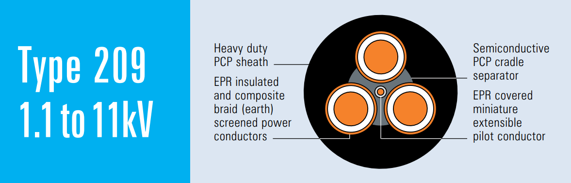
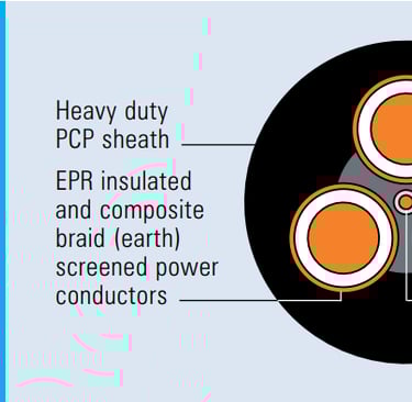
Key Features
The distinguishing characteristics of Type 209 cables include:
Three screened power cores for reliable power transmission
A central extensible pilot conductor for control and monitoring
Composite screening system with tinned copper braiding
Heavy-duty elastomeric sheathing for durability in harsh environments
II. Application Scenarios
Underground Coal Mines
These cables serve as main feeders to critical mining equipment including:
Longwall equipment
Belt conveyors
Gate-end power boxes
Trailing Cables for Machinery
Type 209 cables function primarily as flexible feeders to various mining machinery:
Larger cables supply power to pumps, crushers, winches, and hydraulic supports
Smaller diameter variants are used for drills and hand-held tools and equipment
Fixed vs. Reeling Use
According to the documentation, Type 209 series cables are "mainly used as a flexible feeder to machinery, more suitable as a trailing cable rather than for reeling." This makes them ideal for applications where the cable must follow equipment movement without continuous spooling on and off drums
III. Electrical and Mechanical Parameters
Voltage Ratings
Standard operational rating: 1.1/1.1 kV
For higher voltage applications, cables with ratings of 3.3/3.3 kV and above receive additional conductor screening
Conductor
The cables feature flexible stranded tinned annealed copper conductors, available in various cross-sectional areas from 6mm² to 300mm², with specific strand configurations for each size. For example:
6mm²: 84/0.30 (84 strands of 0.30mm diameter)
300mm²: 854/0.67 (854 strands of 0.67mm diameter)
Insulation
The conductors are insulated with Ethylene Propylene Rubber (EPR), with thickness varying based on the voltage rating:
Type 209.1: 1.5-3.0mm insulation thickness
Type 209.3: 3.0mm standard insulation thickness
Type 209.6: 5.0mm insulation thickness
Type 209.11: 7.6mm insulation thickness
Screening
The screening system consists of multiple components:
Conductor Screen: Semiconductive compound (for cables rated 3.3/3.3kV and above)
Insulation Screen: Semiconductive elastomer
Composite Screen (earth conductor): Tinned annealed copper braiding interwoven with polyester yarn
Core Screen area ranges from approximately 7.2mm² to 71.5mm² depending on cable size
Pilot Core
A central extensible pilot conductor features:
EPR-covered flexible stranded tinned copper conductor
Standard 24/0.20 or 40/0.20 strand configuration
0.8mm covering thickness
Sheath
The cables are protected by a heavy-duty Polychloroprene (PCP) sheath:
Thickness ranges from 3.8mm to 10.7mm depending on cable size
Alternative heavy-duty CPE/CSP sheath available upon request
Provides resistance against oils, flames, and mechanical damage
Dimensions and Weight
The documentation provides detailed specifications for each cable variant:
Overall diameter: From 30.0mm (6mm² 209.1) to 109.3mm (300mm² 209.11)
Weight: From 129kg/100m (6mm² 209.1) to 2120kg/100m (300mm² 209.11)
IV. FAQ: Common Mining-Site Issues and Solutions
Moisture Ingress Prevention
Ensure proper gland installation with appropriate compression
Regularly inspect sheath integrity, especially at connection points
Use end-of-drum seals when storing unused sections
Handling Mechanical Damage
Implement regular inspection protocols for cable sheaths
For minor damage, apply approved elastomeric repair tapes
Replace heavily damaged sections to maintain safety integrity
Fault Location Techniques
Utilize time-domain reflectometry (TDR) for pinpointing fault locations
Monitor pilot core continuity for early warning of potential issues
Implement regular insulation resistance testing
Appropriate Applications
Not recommended for shuttle car applications due to specified exclusions
Select appropriate cable size based on current requirements and duty cycle
Consider voltage drop over extended runs when sizing conductors
Service Life Considerations
Under normal conditions, expect 3-5 years of service life
Monitor insulation resistance values to determine replacement timing
Replace after multiple repairs to maintain system integrity
Chemical Exposure Management
The PCP sheath provides good oil resistance
Clean spills promptly and inspect for degradation
Request CPE/CSP sheath variants for environments with specific chemical challenges
Temperature Derating
Follow AS/NZS standards for derating in environments exceeding 40°C
Monitor operating temperature to prevent premature insulation aging
Consider additional ventilation in high-temperature zones
Installation Best Practices
Maintain minimum bend radius (typically 6-8 times overall diameter)
Secure cables to prevent dragging across abrasive surfaces
Allow sufficient slack for equipment movement without tension
Use appropriate cable management systems to minimize mechanical stress