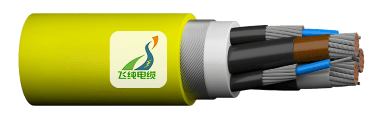
Cable Cross-Sectional Area Selection and Verification in Australia
Selecting the correct cable cross-sectional area represents one of the most critical decisions in electrical installation design. This fundamental choice directly impacts system safety, energy efficiency, and long-term operational costs. In Australia, where diverse climate conditions and unique installation requirements present particular challenges, understanding the proper cable selection methodology becomes even more essential for electrical professionals. The consequences of improper cable sizing extend far beyond simple inconvenience. Undersized cables create immediate safety hazards through overheating, potential fire risks, and premature insulation failure. Conversely, oversized cables, while safer from a thermal perspective, introduce unnecessary costs and may complicate installation in confined spaces. Perhaps more subtly, both scenarios contribute to energy inefficiencies that compound over the cable's operational lifetime, affecting both environmental sustainability and operating expenses. Australian electrical installations operate under the comprehensive framework of AS/NZS 3008.1.1:2017, the definitive standard for cable selection in alternating voltage systems up to 0.6/1 kV. This standard, developed specifically for typical Australian installation conditions, provides the technical foundation for all cable sizing decisions across residential, commercial, and industrial applications. Understanding how to properly apply this standard transforms theoretical knowledge into practical, compliant electrical design.
5/23/202510 min read

Cable Cross-Sectional Area Selection and Verification in Australia
Understanding Cable Cross-Sectional Area: The Foundation of Electrical Design
Cable cross-sectional area, measured in square millimetres (mm²), defines the physical size of the conductor within an electrical cable. This seemingly simple measurement serves as the primary determinant of a cable's current-carrying capacity, much like how the diameter of a water pipe determines its flow capacity. However, unlike water flow, electrical current flow involves complex interactions between conductor material, insulation properties, and environmental conditions.
The relationship between cross-sectional area and current-carrying capacity follows established electrical principles, but practical application requires consideration of multiple interconnected factors. Think of this relationship as similar to traffic flow on a highway: while a wider road can theoretically handle more vehicles, actual capacity depends on weather conditions, traffic patterns, and road maintenance standards.
Four primary factors govern proper cable selection in Australian installations. Current-carrying capacity ensures the cable can safely handle the electrical load without overheating. Voltage drop considerations maintain adequate voltage levels at the load end, preventing equipment malfunction and inefficient operation. Short-circuit temperature rise verification ensures cables can withstand the extreme thermal stresses that occur during fault conditions. Finally, economic considerations balance initial installation costs against long-term energy losses and maintenance requirements.
Current-Carrying Capacity: The Heart of Cable Performance
Current-carrying capacity, or ampacity, represents the maximum continuous current a cable can carry without exceeding its temperature rating. This fundamental parameter depends on the cable's ability to dissipate heat generated by electrical resistance. When current flows through a conductor, it encounters resistance that converts electrical energy into heat. The cable's insulation and surrounding environment determine how effectively this heat can be removed.
Installation conditions dramatically affect current-carrying capacity. A cable installed in free air enjoys excellent heat dissipation, allowing it to carry its full rated current. The same cable buried underground faces restricted heat dissipation, requiring derating to prevent overheating. Similarly, cables installed in building cavities, conduits, or cable trays experience varying degrees of thermal restriction that must be accounted for in the selection process.
Ambient temperature plays a crucial role in determining actual current-carrying capacity. Australian conditions frequently exceed the standard reference temperature of 30°C used in cable rating tables. When ambient temperatures rise, the temperature differential available for heat dissipation decreases, reducing the cable's safe current-carrying capacity. This relationship becomes particularly important in Queensland's tropical climate or during extreme summer conditions across the continent.
Cable grouping effects present another critical consideration often overlooked in practical installations. When multiple cables run together, they create a thermally congested environment where heat dissipation becomes increasingly difficult. AS/NZS 3008.1.1:2017 provides comprehensive derating factors that account for various grouping arrangements, from simple bundled installations to complex tray configurations.
Applying derating factors requires careful analysis of actual installation conditions compared to the standard reference conditions used in cable rating tables. These factors, expressed as multipliers less than unity, reduce the cable's nominal current-carrying capacity to account for adverse installation conditions. The cumulative effect of multiple derating factors can significantly impact cable selection, sometimes requiring substantially larger conductors than initially anticipated.
Voltage Drop: Maintaining System Performance
Voltage drop represents the reduction in voltage that occurs as electrical current travels through a cable's resistance and reactance. While often treated as a secondary consideration, voltage drop significantly impacts system performance, equipment life, and energy efficiency. Understanding voltage drop requires appreciating that electrical energy doesn't flow through cables without cost—the cable's impedance always extracts a toll in the form of voltage reduction.
Australian standards, specifically AS/NZS 3000, establish maximum permissible voltage drop limits to ensure adequate equipment performance. The standard 5% voltage drop limit for final subcircuits represents a careful balance between practical installation constraints and equipment performance requirements. Exceeding these limits can cause motors to draw excessive current, lighting to operate at reduced efficiency, and electronic equipment to malfunction or fail prematurely.
Calculating voltage drop involves understanding the relationship between cable impedance, load current, route length, and power factor. Cable impedance includes both resistance and reactance components, with resistance predominating in smaller cables and reactance becoming more significant in larger conductors. The calculation uses millivolts per ampere-meter (mV/A·m) values provided in AS/NZS 3008.1.1:2017, allowing designers to quickly assess voltage drop for various cable sizes and installation configurations.
Practical voltage drop calculations must consider the complete circuit path, including both active and neutral conductors. For three-phase systems, the calculation methodology differs slightly from single-phase circuits, accounting for the phase relationships between conductors. Power factor, representing the relationship between real and reactive power, significantly influences voltage drop calculations, particularly in circuits supplying motors or other inductive loads.
Long cable runs present particular challenges for voltage drop compliance. In large industrial installations or rural applications where substantial distances separate electrical panels from loads, voltage drop often becomes the controlling factor in cable selection rather than current-carrying capacity. These scenarios frequently require cables significantly larger than those needed purely for current-carrying purposes, highlighting the interconnected nature of cable selection criteria.
Short-Circuit Temperature Rise: Protecting Against Fault Conditions
Short-circuit conditions represent the most severe thermal stress cables experience during their operational life. When a fault occurs, enormous currents can flow for brief periods before protective devices operate to clear the fault. During these events, the cable must withstand extreme temperature rises without suffering permanent damage or creating additional hazards.
The physics of short-circuit heating differs fundamentally from normal current-carrying capacity considerations. During short-circuit conditions, the heating occurs so rapidly that heat dissipation to the surrounding environment becomes negligible. The cable's thermal mass, represented by its cross-sectional area and specific heat capacity, becomes the primary factor determining temperature rise.
AS/NZS 3008.1.1:2017 provides calculation methods for determining minimum cable cross-sectional areas based on short-circuit temperature rise criteria. These calculations use a constant K value that incorporates the cable's thermal properties, maximum operating temperature, and maximum short-circuit temperature. The relationship between fault current magnitude, fault duration, and required cable size follows established thermal relationships that ensure cable integrity during fault conditions.
Determining maximum short-circuit current requires detailed system analysis, considering the impedance of all circuit elements from the supply transformer to the fault location. This analysis typically involves coordination with protection system design, as both fault current magnitude and clearing time influence the cable sizing requirements. Modern electrical design increasingly relies on computer-based fault analysis to accurately determine these parameters for complex electrical systems.
The verification process for short-circuit temperature rise provides an essential safety check that complements normal current-carrying capacity calculations. Even cables selected primarily for voltage drop considerations must demonstrate adequate short-circuit performance, ensuring comprehensive protection under all operating conditions.
Economic Optimization: Balancing Costs and Efficiency
Economic optimization in cable selection extends beyond simple initial cost comparison to encompass total lifecycle costs. While larger cables require higher initial investment, they offer reduced energy losses over their operational lifetime. This trade-off becomes particularly significant in continuously loaded circuits where energy costs accumulate substantially over decades of operation.
AS/NZS 3008.1.1:2017 references IEC 60287-3-2 for economic cable sizing methodology, providing a framework for evaluating lifecycle costs. This approach considers electricity prices, load factors, discount rates, and cable life expectancy to determine the economically optimal conductor size. The methodology recognises that energy costs often dwarf initial cable costs over typical installation lifespans.
Economic analysis becomes most relevant for heavily loaded circuits with high annual operating hours. Industrial installations, particularly those with continuous processes, benefit significantly from economic optimisation. Conversely, residential circuits with intermittent loading may not justify the additional analysis complexity, though energy efficiency considerations remain important for environmental sustainability.
The economic optimisation process requires balancing multiple competing factors. Larger cables reduce energy losses but increase material costs, installation difficulty, and space requirements. Market electricity prices, which vary significantly across Australian states and between commercial tariff structures, substantially influence the optimal solution. Climate considerations, particularly carbon pricing mechanisms, increasingly factor into these economic evaluations.

Step-by-Step Cable Selection Process: A Systematic Approach
Proper cable selection follows a systematic methodology that ensures compliance with all relevant criteria. This process begins with determining the design current (IB), which represents the maximum continuous current the cable must carry under normal operating conditions. Design current calculation requires careful analysis of connected loads, diversity factors, and future expansion requirements.
The next step involves selecting the appropriate installation method and determining applicable derating factors. This selection process requires detailed knowledge of the actual installation conditions, including ambient temperature, grouping arrangements, and thermal environment. AS/NZS 3008.1.1:2017 provides comprehensive tables covering various installation methods, from direct burial to complex tray arrangements.
Once derating factors are established, the required continuous current-carrying capacity (IZ) can be determined. The fundamental relationship IB ≤ IZ ensures the cable can safely carry the design current under the specified installation conditions. This step often involves iterative calculations as different cable sizes and installation arrangements are evaluated.
Voltage drop verification provides the next critical check in the selection process. Using the tentatively selected cable size, voltage drop calculations determine whether the installation complies with AS/NZS 3000 requirements. Long circuits or heavily loaded applications frequently require cable upsizing to meet voltage drop criteria, regardless of current-carrying capacity requirements.
Short-circuit temperature rise verification ensures the selected cable can withstand fault conditions without damage. This calculation requires coordination with protection system design to determine maximum fault currents and clearing times. The verification process confirms that the cable's thermal mass provides adequate protection during the most severe fault conditions.
Finally, economic optimization considerations may suggest alternative cable sizes that provide better lifecycle value. This analysis becomes particularly important for high-utilisation circuits where energy savings can justify larger initial investments.
Practical Application: Working Through Real-World Examples
Consider a typical industrial motor circuit requiring 32 amperes design current over a 50-meter cable run. Beginning with current-carrying capacity, AS/NZS 3008.1.1:2017 tables indicate that a 6 mm² cable can carry 32 amperes when installed in free air at 30°C ambient temperature. However, the actual installation involves four cables in a cable tray with 40°C ambient temperature.
Applying derating factors, the ambient temperature correction factor for 40°C reduces capacity to approximately 0.87 of the tabulated value. The grouping factor for four cables in a tray further reduces capacity to 0.80 of the adjusted value. The cumulative derating requires the cable to carry 32/(0.87 × 0.80) = 46 amperes under reference conditions, necessitating selection of a 10 mm² cable.
Voltage drop verification for the 10 mm² cable over 50 meters carrying 32 amperes yields approximately 3.2% voltage drop, well within the 5% limit. Short-circuit analysis, assuming a maximum fault current of 2000 amperes for 0.1 seconds, confirms that 10 mm² provides adequate thermal capacity for fault conditions.
This example illustrates how derating factors can substantially influence cable selection, often requiring cables significantly larger than initial current-carrying capacity calculations suggest. The systematic approach ensures all criteria receive proper consideration, preventing oversights that could compromise safety or performance.
A residential example might involve a 20-ampere circuit supplying outdoor lighting over a 40-meter underground run. While a 2.5 mm² cable provides adequate current-carrying capacity, voltage drop calculations reveal approximately 6.8% voltage drop, exceeding AS/NZS 3000 limits. Upgrading to 4 mm² cable reduces voltage drop to 4.3%, ensuring compliant operation while maintaining adequate current-carrying capacity and fault performance.
Common Pitfalls and Professional Best Practices
Professional cable selection requires vigilance against common mistakes that can compromise installation safety and performance. Perhaps the most frequent oversight involves inadequate consideration of derating factors, particularly in complex installations where multiple factors apply simultaneously. Engineers and electricians must carefully evaluate actual installation conditions rather than relying on simplified assumptions about cable capacity.
Voltage drop considerations often receive insufficient attention, particularly in cost-sensitive projects where larger cables appear unnecessarily expensive. However, the long-term consequences of excessive voltage drop, including increased energy consumption and reduced equipment life, typically far exceed the additional cable costs. Professional practice requires explaining these relationships to clients who may not immediately appreciate the lifecycle benefits of proper cable sizing.
Temperature considerations present another area prone to errors, particularly in Australia's diverse climate conditions. Standard cable rating tables assume 30°C ambient temperature, but many Australian locations regularly exceed this assumption. Professional designers must adjust for local climate conditions, considering both average temperatures and extreme conditions that may occur during the installation's operational life.
Modern electrical design increasingly relies on computer-based calculation tools that can handle complex derating factor interactions and provide rapid comparison of alternative cable sizes. However, these tools require careful input of actual installation parameters and validation of results against fundamental principles. The most sophisticated software cannot substitute for thorough understanding of underlying cable selection principles.
Regular consultation of current standards ensures designs remain compliant with evolving requirements. AS/NZS 3008.1.1:2017 undergoes periodic updates that may affect cable selection methodology or available products. Professional practice requires staying current with these changes and understanding their implications for ongoing projects.
Manufacturer data provides essential information for specific products that may offer performance advantages over generic standard values. Cable manufacturers often provide detailed technical data that enables more precise calculations, particularly for specialised applications or installation conditions not fully covered by standard tables.
Conclusion: Excellence Through Systematic Application
Proper cable cross-sectional area selection represents a fundamental skill that underpins safe, efficient electrical installations throughout Australia. The systematic methodology outlined in AS/NZS 3008.1.1:2017 provides a comprehensive framework for addressing the complex interactions between current-carrying capacity, voltage drop, short-circuit performance, and economic considerations.
The interconnected nature of these selection criteria demands careful attention to detail and thorough understanding of underlying principles. Each factor influences the others, creating a complex optimisation problem that requires both technical knowledge and practical experience to solve effectively. The most successful electrical professionals develop intuitive understanding of these relationships while maintaining rigorous adherence to systematic calculation procedures.
Australian electrical installations face unique challenges from climate extremes, diverse installation conditions, and evolving energy efficiency requirements. These factors emphasise the importance of thorough cable selection procedures that account for local conditions while maintaining compliance with national standards. The investment of time and effort in proper cable selection pays dividends through decades of safe, efficient operation.
Continuous learning remains essential as electrical technology evolves and standards develop. The principles outlined in this guide provide a solid foundation, but professional growth requires ongoing study of emerging technologies, updated standards, and evolving best practices. The electrical industry's commitment to safety and efficiency depends on professionals who understand these principles and apply them consistently in their daily practice.
The path to excellence in cable selection begins with thorough understanding of fundamental principles and develops through consistent application of systematic procedures. By following the methodologies outlined in AS/NZS 3008.1.1:2017 and maintaining awareness of practical considerations, electrical professionals can ensure their installations meet the highest standards of safety, efficiency, and reliability that Australian conditions demand.
References
AS/NZS 3008.1.1:2017 – Electrical installations – Selection of cables – Cables for alternating voltages up to and including 0.6/1 kV – Typical Australian installation conditions.
AS/NZS 3000 – Electrical installations (Australian/New Zealand Wiring Rules).
IEC 60287-3-2 – Electric cables – Calculation of the current rating – Part 3-2: Sections on economic optimization.