How to Calculate the Bending Radius of the Cable?
In power engineering, excessive cable bending can lead to insulation damage, conductor breakage, and other hidden dangers. A nuclear power plant once experienced a short circuit due to insufficient cable bending radius, resulting in direct losses exceeding one million dollars. Correctly calculating the bending radius is a key technology for ensuring cable longevity and safe operation.
5/7/20252 min read
Introduction: Why is Bending Radius Important?
In power engineering, excessive cable bending can lead to insulation damage, conductor breakage, and other hidden dangers. A nuclear power plant once experienced a short circuit due to insufficient cable bending radius, resulting in direct losses exceeding one million dollars. Correctly calculating the bending radius is a key technology for ensuring cable longevity and safe operation.
How to Calculate the Bending Radius of the Cable?
I. Core Concept Analysis
Definition of Bending Radius: The radius of the inner arc (R) when a cable is bent, directly related to the cable's outer diameter (D)
Minimum Bending Radius: The minimum allowable value that ensures the cable's structural integrity, typically a multiple of D
Destructive Bending Case Study: A wind farm using a 6×D bending radius led to armor layer deformation, reducing cable life by 40%
II. Key Influencing Factors
Cable Structure (coefficient comparison):
Single-core non-armored: 12×D
Multi-core armored: 15×D
Fiber composite cable: 20×D
Material Characteristics:
PVC insulation layers endure 30% fewer bending cycles than XLPE
Aluminum alloy conductors have 15% higher bending elasticity than copper conductors
Environmental Parameters:
Low temperature (-20°C) requires a 20% increase in bending radius
Dynamic bending conditions require 1.5 times larger radius than static conditions
III. International Standards and Calculation Formulas
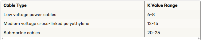
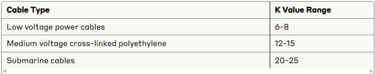
1.IEC 60287 Standard: Rmin = K×D K value table:
2.Dynamic Bending Formula: R = (E×I)/(M×σ)
E: Elastic modulus
I: Sectional moment of inertia
σ: Allowable stress
3.Engineering Quick Calculation Techniques:
Palm rule: Adult palm length ≈ 15×D (suitable for 10kV cables)
Conduit verification: Conduit diameter ≥ 10× cable diameter
IV. Practical Steps (Using a 10kV Armored Cable as an Example)
Measure the outer diameter: Use a π tape to obtain D=58mm
Check standards to determine K value: Choose 15 for armored multi-core cables
Calculate Rmin = 15×58 = 870mm
Installation control:
Use a guide wheel with 900mm radius
Set bending limit markers
Verify with a thermal imaging camera that temperature rise at bending points is < 3°C
V. Common Errors and Solutions
Error: Bending multiple cables together as a bundle Improvement: Adopt layered offset bending with spacing maintained at 2×D
Error: Ignoring slack cable coiling radius Solution: When using serpentine layouts, amplitude should be > 5×Rmin
Error: Using sharp angle bends Solution: Use three-section 135° bends in combination instead of 90° right angles
VI. Smart Detection Technology
Fiber-optic Sensing: Embed strain-sensing optical fibers for real-time bending deformation monitoring
3D Laser Scanning: Build curved surface models with deviation detection accuracy of ±2mm
Machine Learning Prediction: Life prediction models based on historical data with accuracy > 85%