How to Choose Cable Size? A Beginner's Guide
Whether you're wiring a new home, setting up industrial equipment, or installing a renewable energy system, choosing the correct cable size is crucial for safety and efficiency. Undersized cables can overheat, create dangerous voltage drops, and even cause fires, while oversized cables waste money unnecessarily. The proper cable size ensures that electrical current flows safely through your system while maintaining voltage levels within acceptable parameters. This guide will walk you through the essential factors to consider when selecting electrical cables, helping you make informed decisions for your projects.
5/7/20256 min read
How to Choose Cable Size? A Beginner's Guide
I. Introduction
Whether you're wiring a new home, setting up industrial equipment, or installing a renewable energy system, choosing the correct cable size is crucial for safety and efficiency. Undersized cables can overheat, create dangerous voltage drops, and even cause fires, while oversized cables waste money unnecessarily.
The proper cable size ensures that electrical current flows safely through your system while maintaining voltage levels within acceptable parameters. This guide will walk you through the essential factors to consider when selecting electrical cables, helping you make informed decisions for your projects.
II. Key Factors in Choosing Cable Size
1. Current Carrying Capacity (Amperage)
Definition and relevance
Current carrying capacity (ampacity) refers to the maximum current a conductor can safely carry continuously without exceeding its temperature rating. This is the primary factor in determining cable size.
How to estimate or calculate the current load
To determine current load:
For specific appliances: Check the nameplate for amperage or wattage ratings
For circuits: Add up the expected loads or use the formula I = P/V (Current = Power/Voltage)
For motors: Account for starting current, which can be 3-7 times the running current
Always include a safety margin of 20-25% above your calculated load
2. Voltage Drop
What it is and why it matters
Voltage drop is the reduction in voltage that occurs as electricity travels through a cable. When voltage drops significantly, equipment performance suffers, motors can overheat, and electronic devices may malfunction or fail prematurely.
Acceptable voltage drop limits
General applications: Maximum 3% voltage drop
Lighting circuits: Maximum 2% drop recommended
Motor starting: Up to 5% drop may be acceptable temporarily
Critical equipment: Consider tighter restrictions (1-2%)
The longer the cable run, the more significant the voltage drop becomes, requiring larger cable sizes to compensate.
3. Cable Length
How cable length affects resistance and voltage drop
Cable resistance increases proportionally with length. Doubling the cable length doubles the resistance and voltage drop. This means that what works for a 10-meter run may be completely inadequate for a 50-meter run, even with the same load.
Special considerations for long-distance runs
For runs exceeding 30 meters, voltage drop often becomes the determining factor rather than ampacity
Very long runs may require jumping up multiple cable sizes
Consider alternative approaches for very long distances:
Higher voltage transmission with step-down transformers
Multiple feed points
DC power for some applications
4. Type of Load
Resistive vs inductive loads
Resistive loads (heaters, incandescent lights): Draw consistent current based on their power rating
Inductive loads (motors, compressors, transformers): Draw high inrush current at startup and create power factor considerations
Impact on sizing
Motors typically require oversized cables to handle starting current
For circuits with multiple motors, consider diversity factors based on the likelihood of simultaneous operation
Power factor correction equipment may reduce overall current requirements
5. Ambient Temperature and Installation Conditions
Temperature correction factors
The standard ampacity ratings for cables assume an ambient temperature of about 30°C (86°F). For higher temperatures, cables must be derated:
At 40°C (104°F): Reduce capacity by approximately 10-15%
At 50°C (122°F): Reduce capacity by approximately 20-30%
At 60°C (140°F): Reduce capacity by approximately 40-45%
Installation methods affecting capacity
Buried cables: Heat dissipation depends on soil type and moisture content
Conduit use: Restricts heat dissipation, reducing capacity, especially for multiple cables
Cable grouping: Bundles of cables generate more heat, requiring derating
Insulation type: Different insulation materials have different temperature ratings
6. Material of the Conductor
Copper vs aluminum comparison
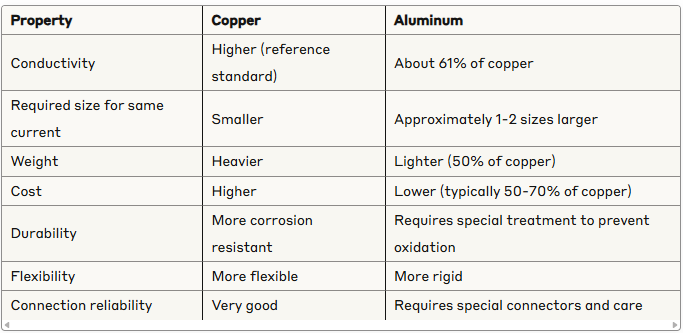
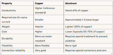
Aluminum is often chosen for large feeders and service entrances where cost and weight are significant factors, while copper is preferred for most branch circuits and critical applications.
III. Common Cable Size Standards
Overview of standards
American Wire Gauge (AWG)
Used primarily in North America
Counter-intuitive: Larger numbers indicate smaller wires
Common sizes: 14 AWG (15A circuits), 12 AWG (20A circuits), 10 AWG (30A circuits)
Metric system (mm²)
Used internationally and in IEC standards
Directly represents the cross-sectional area of the conductor
Common sizes: 1.5 mm², 2.5 mm², 4 mm², 6 mm², 10 mm², etc.
Regulatory standards
National Electrical Code (NEC): Used in the US
International Electrotechnical Commission (IEC): International standard
BS7671: British standards
Local building codes and regulations may have specific requirements
Example cable sizing table
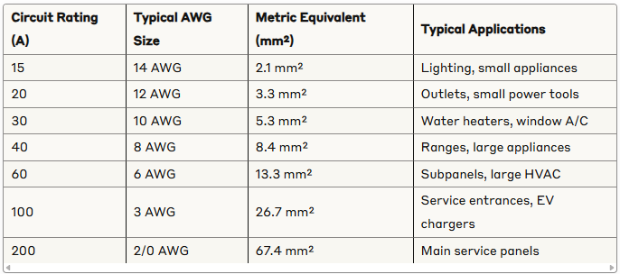
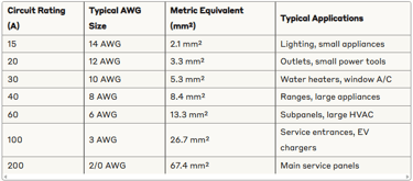
Note: This table is for general reference only. Actual requirements depend on all factors discussed in this guide and local electrical codes.
IV. Cable Sizing Calculation Methods
1. Manual Calculation
Basic voltage drop formula:
VD = (2 × L × I × R) / 1000
Where:
VD = Voltage Drop (V)
L = Cable length (one-way, in meters)
I = Current (A)
R = Cable resistance (Ω/km)
Simplified cable size selection:
Determine the maximum current (including safety margin)
Select cable that exceeds this current rating
Calculate voltage drop based on length
If voltage drop exceeds limits, increase cable size
2. Using Online Calculators or Software
Many free and paid tools are available to simplify cable sizing:
Manufacturer-provided calculators (Southwire, General Cable)
Professional electrical design software (e.g., ETAP, EasyPower)
Mobile apps for quick field calculations
These tools typically account for factors like:
Cable type and material
Installation method
Ambient temperature
Grouping factors
Voltage drop requirements
3. When to Consult an Electrician or Engineer
Consider professional help when:
Working with three-phase power systems
Designing critical infrastructure
Handling large loads (>30A)
Working in hazardous environments
Dealing with unusual installation conditions
When local codes require professional certification
V. Real-World Examples
Example 1: Choosing cable for a 10A light circuit at home
Scenario:
Circuit: 120V lighting circuit drawing 10A
Distance: 15 meters from panel to furthest fixture
Installation: In-wall, normal residential conditions
Solution:
Current requirement: 10A × 1.25 (safety margin) = 12.5A
Initial cable size based on ampacity: 14 AWG (15A rating)
Voltage drop check:
14 AWG copper has resistance of approximately 8.3 Ω/km
VD = (2 × 15 × 10 × 8.3) / 1000 = 2.49V
As percentage: 2.49V / 120V × 100% = 2.08%
Decision: 14 AWG is suitable as voltage drop is under 3%
Example 2: Selecting cable for a 5kW motor 50 meters away
Scenario:
5kW three-phase motor, 400V, power factor 0.85
Distance: 50 meters
Installation: In conduit, ambient temperature 35°C
Solution:
Current calculation:
I = 5000 / (√3 × 400 × 0.85) = 8.5A
Starting current: 8.5A × 6 = 51A (momentary)
With 25% margin: 8.5A × 1.25 = 10.6A continuous
Initial cable size based on ampacity: 2.5 mm² (carrying capacity ~20A)
Temperature derating: At 35°C, derate by ~5% → 19A (still sufficient)
Voltage drop check:
2.5 mm² has resistance approximately 7.41 Ω/km
VD = (√3 × 50 × 10.6 × 7.41) / 1000 = 6.8V
As percentage: 6.8V / 400V × 100% = 1.7%
Starting voltage drop check:
VD during start = (√3 × 50 × 51 × 7.41) / 1000 = 32.7V
As percentage: 32.7V / 400V × 100% = 8.2%
Decision: Consider increasing to 4 mm² to reduce voltage drop during starting, especially if motor starts frequently or under load
VI. Safety and Regulations
Importance of adhering to electrical codes
Electrical codes exist to protect life and property. They represent the minimum safety requirements based on extensive research and experience. Common codes include:
NEC (National Electrical Code): Updated every three years in the US
CEC (Canadian Electrical Code): Canadian equivalent of NEC
IEC standards: International standards adopted by many countries
Local building codes: May have additional requirements specific to your location
Certification and labeling of cables
Look for these markings to ensure cables meet safety standards:
UL (Underwriters Laboratories) or ETL certification
CE marking in Europe
Type designations (e.g., THHN, XHHW, NM-B)
Temperature rating (e.g., 60°C, 75°C, 90°C)
Voltage rating (e.g., 300V, 600V)
Size markings (AWG or mm²)
Fire safety and insulation types
Different insulation types offer varying levels of protection:
PVC (Thermoplastic): Common, economical, but produces toxic smoke when burned
XLPE (Cross-linked polyethylene): Better heat resistance and durability
Low-smoke zero-halogen (LSZH): Safer in fires, required in many public buildings
Mineral insulated (MI): Highest fire rating, used in critical circuits
For critical applications or public buildings, always consider fire performance alongside electrical requirements.
VII. Conclusion
Key takeaways
Safety first: When in doubt, choose the larger cable size
Consider all factors: Current, length, voltage drop, environment, and load type all matter
Follow codes: Local electrical codes set minimum requirements
Think long-term: Future expansion may justify larger cables now
Consult professionals: For critical or complex installations
Final tips
Always overestimate rather than underestimate your needs
For DIY projects, have your work inspected by a professional
Document your installations with diagrams and calculations
Consider future needs when sizing cables for new construction
Remember that the cost difference between cable sizes is often minor compared to the cost of reinstallation
VIII. Resources and Tools
Useful calculators and references
Southwire Voltage Drop Calculator
Cerrowire Electrical Calculator
BlueSeaSystem's Circuit Wizard
Standards and guidance documents
NFPA 70 (National Electrical Code) - Available at NFPA.org
IEEE 141 (Red Book) - Power distribution for industrial plants
IEEE 242 (Buff Book) - Protection and coordination of industrial power systems
Books for further reading
"Ugly's Electrical References" - A compact reference guide
"Practical Electrical Wiring" by Herbert P. Richter and W. Creighton Schwan
"National Electrical Code Handbook" published by NFPA
Remember that while this guide gives you the fundamentals of cable sizing, electrical work can be dangerous and often requires professional licensing. Always consult with qualified electricians or engineers for critical installations and follow all local codes and regulations.