N)TSCGECWÖU – TBM Tunneling Cable
Discover the technical specifications, applications, and electrical parameters of (N)TSCGECWÖU TBM tunneling cables for underground mining and tunnel construction projects. Learn about their robust design, operating characteristics, and installation requirements.
6/6/202521 min read
(N)TSCGECWÖU – TBM Tunneling Cable
Introduction
The construction of modern underground infrastructure represents one of the most challenging engineering endeavors of our time. Beneath the bustling streets of major cities across Germany and Europe, tunnel boring machines (TBMs) work tirelessly to create the vital arteries that will carry tomorrow's transportation networks, utility systems, and mining operations. These mechanical marvels, often spanning several hundred meters in length and weighing thousands of tons, require sophisticated power and control systems to function effectively in the harsh underground environment.
At the heart of every successful TBM operation lies a critical component that often goes unnoticed by the general public yet plays an indispensable role in the entire project's success: the specialized power cable. The (N)TSCGECWÖU cable, specifically designed for tunnel boring machine applications, represents decades of engineering innovation aimed at solving the unique challenges posed by underground construction and mining operations.
Understanding the significance of tunnel boring machines in modern infrastructure development requires us to consider their role in creating the underground networks that form the backbone of urban civilization. From the extensive U-Bahn systems that connect German cities to the complex utility tunnels that carry water, gas, and telecommunications beneath our feet, TBMs have revolutionized how we approach underground construction. These machines can bore through solid rock, navigate complex geological formations, and maintain precise alignment over distances measured in kilometers, all while operating in environments that would be impossible for traditional construction methods.
The critical importance of reliable power supply in these operations cannot be overstated. Unlike surface construction equipment that can be easily accessed for maintenance or emergency repairs, TBMs operate in confined spaces where any interruption in power supply can result in costly delays, safety hazards, and potentially catastrophic equipment damage. The specialized cables that feed power to these machines must therefore meet extraordinarily demanding requirements for durability, flexibility, and reliability that far exceed those of conventional industrial cables.
Application Scenarios and Operating Environment
The (N)TSCGECWÖU cable finds its primary application in the demanding world of tunnel boring machine operations, where it serves as the vital lifeline connecting these massive machines to their power sources. To truly appreciate the engineering challenges that this cable must overcome, we need to examine the specific environments and conditions in which TBMs operate.
Tunnel boring machines typically operate in environments that combine multiple stress factors simultaneously. The primary application scenarios include major infrastructure projects such as subway tunnel construction, where machines must maintain continuous operation for months or even years while boring through varying geological conditions. In these applications, the cable must provide reliable power transmission while being constantly wound and unwound on massive cable reels as the TBM advances through the tunnel.
Mining operations present another critical application scenario, where the cable serves both TBMs and other heavy mining equipment in reeling and trailing configurations. Underground mining environments introduce additional challenges, including exposure to potentially explosive atmospheres, chemical contaminants, and the need for equipment that can operate safely in confined spaces with limited ventilation.
The environmental challenges faced by TBM cables are particularly severe and multifaceted. Mechanical stresses represent perhaps the most significant challenge, as the cable must withstand constant flexing, twisting, and tensile loads as it follows the TBM's movement through the tunnel. Unlike stationary installations where cables remain in fixed positions, TBM cables experience continuous dynamic loading that can quickly fatigue conventional cable designs.
Moisture exposure presents another critical challenge, as underground environments are typically characterized by high humidity levels and frequent contact with groundwater. The cable must maintain its electrical integrity even when subjected to prolonged exposure to water, which can penetrate cable jackets and cause insulation breakdown in poorly designed systems.
Chemical exposure varies significantly depending on the specific geological conditions and construction methods employed. TBMs often encounter aggressive chemical environments, including acidic groundwater, alkaline concrete slurries used in tunnel lining, and various industrial chemicals used in the boring process. The cable's outer sheath must resist degradation from these chemicals while maintaining its mechanical properties over extended periods.
Temperature variations add another layer of complexity to the operating environment. Deep underground installations may experience relatively stable temperatures, but the heat generated by TBM operations, combined with the thermal cycling caused by starting and stopping equipment, creates challenging thermal conditions that can accelerate cable degradation if not properly managed.
The confined nature of underground spaces also imposes unique constraints on cable design and installation. TBM cables must be sufficiently flexible to navigate tight curves and confined spaces while maintaining adequate bend radius to prevent internal damage. The cable must also be designed to minimize its overall diameter while providing the necessary electrical capacity, as space constraints in tunnel environments are often severe.


Cable Structure and Design Philosophy
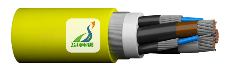
The (N)TSCGECWÖU cable represents a sophisticated engineering solution that addresses each of the challenges outlined above through careful attention to every aspect of its construction. Understanding the cable's structure requires us to examine each component layer by layer, from the innermost conductor to the outermost protective sheath.
The foundation of any power cable lies in its conductors, and the (N)TSCGECWÖU cable employs flexible tinned electrolytic copper conductors manufactured to DIN VDE 0295 Class 5 specifications. This choice of conductor material and construction reflects a careful balance between electrical performance and mechanical durability. The use of electrolytic copper ensures excellent electrical conductivity, which is crucial for minimizing power losses during transmission, particularly important in long cable runs typical of TBM applications.
The tinning process, where the copper conductors are coated with a thin layer of tin, provides crucial protection against corrosion in the demanding underground environment. This protective coating prevents the formation of copper oxides that could increase electrical resistance and compromise the cable's performance over time. The Class 5 flexibility rating indicates that the conductors are constructed from a large number of very fine wire strands, providing the mechanical flexibility necessary to withstand the constant flexing experienced in TBM applications.
The insulation system represents perhaps the most critical aspect of the cable's design, as it must provide reliable electrical isolation while withstanding the mechanical and environmental stresses of underground operation. The cable employs 3GI3 type EPR (Ethylene Propylene Rubber) compound, which offers exceptional performance in demanding applications. EPR insulation provides excellent electrical properties, including high dielectric strength and low dielectric losses, which are essential for maintaining power quality in high-voltage applications.
The thermal properties of EPR insulation make it particularly well-suited for TBM applications, where cables may experience significant temperature variations during operation. Unlike some other insulation materials that become brittle at low temperatures or soften excessively at high temperatures, EPR maintains its mechanical properties across a wide temperature range, ensuring reliable performance in varying underground conditions.
One of the most sophisticated aspects of the cable's design is its electrical field control system, which consists of inner and outer semiconductive layers of specialized rubber compounds. These layers serve a critical function in managing electrical stress distribution within the cable, particularly at the interface between the conductor and insulation. In high-voltage applications, electrical stress concentrations can lead to partial discharges that gradually degrade the insulation and ultimately cause cable failure.
The semiconductive layers work by providing a controlled conductive path that smooths the electrical field distribution, eliminating the sharp electrical stress concentrations that could otherwise occur. This design feature significantly extends the cable's operational life and reliability, which is particularly important in TBM applications where cable replacement would be extremely difficult and costly.
The protective earth conductor system represents another crucial safety feature of the cable design. Each power core is surrounded by a protective earth conductor consisting of tinned copper wires combined with textile braiding, laid concentrically around the power core. This design provides multiple benefits, including enhanced mechanical protection for the power cores, improved grounding performance, and additional safety protection in the event of insulation failure.
The core identification system uses a practical color-coding scheme designed for easy identification during installation and maintenance. Main power cores feature natural coloring with black semiconductive rubber, while control cores are identified with black coloring. This clear identification system helps prevent wiring errors during installation and maintenance operations, which is particularly important in the confined spaces typical of TBM applications.
The cable's sheathing system employs a dual-layer approach designed to provide comprehensive protection against mechanical damage and environmental degradation. The inner sheath consists of GM1b type EPR compound, which provides excellent mechanical protection while maintaining flexibility. This inner sheath serves as the primary barrier against moisture ingress and mechanical damage to the internal cable components.
The outer sheath represents the cable's primary defense against the harsh underground environment. Constructed from 5GM5 type elastomer compound in a distinctive red color, this outer sheath provides exceptional resistance to abrasion, oil, and chemical attack. The choice of elastomer material ensures that the sheath maintains its flexibility and protective properties even after prolonged exposure to the aggressive conditions typical of underground construction sites.
Electrical Parameters and Performance Characteristics
The electrical performance of the (N)TSCGECWÖU cable has been carefully engineered to meet the demanding requirements of TBM applications while providing the safety margins necessary for reliable long-term operation. Understanding these parameters requires us to examine both the basic electrical ratings and the more complex performance characteristics that determine the cable's suitability for specific applications.
The cable is available in multiple voltage ratings to accommodate different TBM power system requirements. The voltage ratings of 3.6/6kV, 6/10kV, 8.7/15kV, 12/20kV, and 18/30kV provide flexibility in system design while ensuring compatibility with various TBM power systems. These ratings follow the standard European notation where the first value represents the voltage between any conductor and earth, while the second value represents the voltage between conductors.
The significance of these voltage ratings becomes apparent when we consider the power requirements of modern TBMs. These machines typically require several megawatts of electrical power to operate their cutting heads, conveyor systems, hydraulic pumps, and ventilation equipment. Higher voltage ratings allow for more efficient power transmission over the long cable runs typical of TBM applications, reducing power losses and improving overall system efficiency.
The AC test voltage specifications provide insight into the cable's electrical strength and safety margins. With test voltages ranging from 11kV to 43kV depending on the cable specification, these values represent the voltage levels at which the cable can safely operate without risk of insulation breakdown. These test voltages are typically applied for specified periods during manufacturing quality control and field testing procedures.
The maximum permissible operating voltage specifications provide crucial information for system designers and operators. For AC applications, the cable can safely operate at voltages up to 20.8/36kV, while DC applications can utilize voltages up to 27/54kV. The higher DC voltage ratings reflect the different stress patterns that DC voltages place on cable insulation systems compared to AC voltages.
Understanding the thermal characteristics of the cable is essential for proper application and installation. The operating temperature range of -40°C to +80°C for fixed installations and -25°C to +80°C for mobile applications reflects the cable's ability to function reliably across the temperature extremes encountered in underground environments. The lower temperature limit for mobile applications acknowledges the additional mechanical stresses that mobile cables experience, which can become more severe at extremely low temperatures.
The current carrying capacity of the cable, determined according to DIN VDE 0298 Part 4, depends on various factors including installation method, ambient temperature, and thermal resistance of the surrounding environment. In TBM applications, these factors can vary significantly as the machine progresses through different geological formations and tunnel sections, requiring careful consideration during system design.
Mechanical Properties and Installation Requirements
The mechanical properties of the (N)TSCGECWÖU cable are specifically designed to meet the demanding requirements of TBM applications, where the cable must withstand constant movement, flexing, and mechanical stress while maintaining its electrical integrity. These properties represent some of the most challenging aspects of cable design for mobile applications.
The minimum bending radius specification, established according to DIN VDE 0298 Part 3, provides crucial guidance for cable installation and routing. This specification ensures that the cable is not bent beyond its design limits, which could cause internal damage to conductors, insulation, or other cable components. In TBM applications, proper attention to bending radius is particularly important due to the confined spaces and complex routing paths typically encountered.
The maximum tensile load specification of 15 N/mm² provides important guidance for cable handling and installation procedures. This value represents the maximum pulling force that can be safely applied to the cable during installation without causing damage to its internal structure. In TBM applications, where cables must often be pulled through long distances and around obstacles, proper attention to tensile load limits is essential for preventing installation damage.
The torsion specification of 25°/m addresses the twisting forces that TBM cables experience during operation. As TBMs navigate curves and changes in direction, the trailing cable experiences complex torsional loads that can damage conventional cable designs. The 25°/m specification ensures that the cable can withstand these torsional forces without internal damage.
The travel speed specification of up to 30 m/min for TBM applications reflects the dynamic nature of these installations. Unlike stationary power cables that remain in fixed positions throughout their operational life, TBM cables must follow the machine's movement while maintaining reliable power transmission. The 30 m/min specification ensures that the cable can accommodate the typical advance rates of modern TBMs without mechanical stress or electrical performance degradation.
The minimum distance for change of direction specification of 20 times the cable diameter provides guidance for installation planning and cable routing. This specification ensures that the cable is not subjected to sharp direction changes that could cause internal damage or premature failure. In practice, this means that cable routing systems must be carefully planned to provide adequate space for proper cable management.
Cross-Sectional Configurations and Technical Specifications
The (N)TSCGECWÖU cable is available in various cross-sectional configurations to meet different power and control requirements. Understanding these configurations is essential for proper cable selection and system design. Each configuration is identified by a specific notation that describes the conductor arrangement and cross-sectional areas.
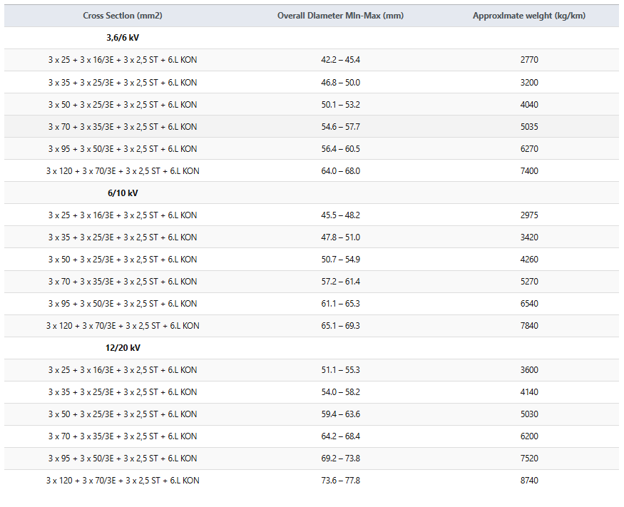
For 3.6/6kV applications, the available configurations range from 3x25+3x16/3E+3x25ST+6ULKON to 3x120+3x70/3E+3x25ST+6ULKON. This notation describes the main power conductors, control conductors, earth conductors, and additional control circuits included in each cable. The progression from smaller to larger cross-sectional areas allows for different current carrying capacities to match specific TBM power requirements.
The overall diameter specifications, ranging from approximately 42.2-45.4mm for the smallest configuration to 64.0-68.0mm for the largest in the 3.6/6kV range, provide important information for cable routing and installation planning. These dimensions must be considered when designing cable management systems, conduits, and support structures.
The approximate weight specifications, ranging from 2770 kg/km to 7400 kg/km for 3.6/6kV configurations, have significant implications for cable handling, installation, and support system design. These weights represent substantial loads that must be properly supported throughout the cable's length to prevent mechanical damage and ensure reliable operation.
Similar configuration options are available for higher voltage ratings, with 6/10kV and 12/20kV versions offering comparable cross-sectional arrangements adapted for their respective voltage levels. The progression to higher voltage ratings typically involves increased insulation thickness, which results in larger overall diameters and weights for equivalent conductor cross-sections.Cable Structure and Design Philosophy
The (N)TSCGECWÖU cable represents a sophisticated engineering solution that addresses each of the challenges outlined above through careful attention to every aspect of its construction. Understanding the cable's structure requires us to examine each component layer by layer, from the innermost conductor to the outermost protective sheath.
The foundation of any power cable lies in its conductors, and the (N)TSCGECWÖU cable employs flexible tinned electrolytic copper conductors manufactured to DIN VDE 0295 Class 5 specifications. This choice of conductor material and construction reflects a careful balance between electrical performance and mechanical durability. The use of electrolytic copper ensures excellent electrical conductivity, which is crucial for minimizing power losses during transmission, particularly important in long cable runs typical of TBM applications.
The tinning process, where the copper conductors are coated with a thin layer of tin, provides crucial protection against corrosion in the demanding underground environment. This protective coating prevents the formation of copper oxides that could increase electrical resistance and compromise the cable's performance over time. The Class 5 flexibility rating indicates that the conductors are constructed from a large number of very fine wire strands, providing the mechanical flexibility necessary to withstand the constant flexing experienced in TBM applications.
The insulation system represents perhaps the most critical aspect of the cable's design, as it must provide reliable electrical isolation while withstanding the mechanical and environmental stresses of underground operation. The cable employs 3GI3 type EPR (Ethylene Propylene Rubber) compound, which offers exceptional performance in demanding applications. EPR insulation provides excellent electrical properties, including high dielectric strength and low dielectric losses, which are essential for maintaining power quality in high-voltage applications.
The thermal properties of EPR insulation make it particularly well-suited for TBM applications, where cables may experience significant temperature variations during operation. Unlike some other insulation materials that become brittle at low temperatures or soften excessively at high temperatures, EPR maintains its mechanical properties across a wide temperature range, ensuring reliable performance in varying underground conditions.
One of the most sophisticated aspects of the cable's design is its electrical field control system, which consists of inner and outer semiconductive layers of specialized rubber compounds. These layers serve a critical function in managing electrical stress distribution within the cable, particularly at the interface between the conductor and insulation. In high-voltage applications, electrical stress concentrations can lead to partial discharges that gradually degrade the insulation and ultimately cause cable failure.
The semiconductive layers work by providing a controlled conductive path that smooths the electrical field distribution, eliminating the sharp electrical stress concentrations that could otherwise occur. This design feature significantly extends the cable's operational life and reliability, which is particularly important in TBM applications where cable replacement would be extremely difficult and costly.
The protective earth conductor system represents another crucial safety feature of the cable design. Each power core is surrounded by a protective earth conductor consisting of tinned copper wires combined with textile braiding, laid concentrically around the power core. This design provides multiple benefits, including enhanced mechanical protection for the power cores, improved grounding performance, and additional safety protection in the event of insulation failure.
The core identification system uses a practical color-coding scheme designed for easy identification during installation and maintenance. Main power cores feature natural coloring with black semiconductive rubber, while control cores are identified with black coloring. This clear identification system helps prevent wiring errors during installation and maintenance operations, which is particularly important in the confined spaces typical of TBM applications.
The cable's sheathing system employs a dual-layer approach designed to provide comprehensive protection against mechanical damage and environmental degradation. The inner sheath consists of GM1b type EPR compound, which provides excellent mechanical protection while maintaining flexibility. This inner sheath serves as the primary barrier against moisture ingress and mechanical damage to the internal cable components.
The outer sheath represents the cable's primary defense against the harsh underground environment. Constructed from 5GM5 type elastomer compound in a distinctive red color, this outer sheath provides exceptional resistance to abrasion, oil, and chemical attack. The choice of elastomer material ensures that the sheath maintains its flexibility and protective properties even after prolonged exposure to the aggressive conditions typical of underground construction sites.
Electrical Parameters and Performance Characteristics
The electrical performance of the (N)TSCGECWÖU cable has been carefully engineered to meet the demanding requirements of TBM applications while providing the safety margins necessary for reliable long-term operation. Understanding these parameters requires us to examine both the basic electrical ratings and the more complex performance characteristics that determine the cable's suitability for specific applications.
The cable is available in multiple voltage ratings to accommodate different TBM power system requirements. The voltage ratings of 3.6/6kV, 6/10kV, 8.7/15kV, 12/20kV, and 18/30kV provide flexibility in system design while ensuring compatibility with various TBM power systems. These ratings follow the standard European notation where the first value represents the voltage between any conductor and earth, while the second value represents the voltage between conductors.
The significance of these voltage ratings becomes apparent when we consider the power requirements of modern TBMs. These machines typically require several megawatts of electrical power to operate their cutting heads, conveyor systems, hydraulic pumps, and ventilation equipment. Higher voltage ratings allow for more efficient power transmission over the long cable runs typical of TBM applications, reducing power losses and improving overall system efficiency.
The AC test voltage specifications provide insight into the cable's electrical strength and safety margins. With test voltages ranging from 11kV to 43kV depending on the cable specification, these values represent the voltage levels at which the cable can safely operate without risk of insulation breakdown. These test voltages are typically applied for specified periods during manufacturing quality control and field testing procedures.
The maximum permissible operating voltage specifications provide crucial information for system designers and operators. For AC applications, the cable can safely operate at voltages up to 20.8/36kV, while DC applications can utilize voltages up to 27/54kV. The higher DC voltage ratings reflect the different stress patterns that DC voltages place on cable insulation systems compared to AC voltages.
Understanding the thermal characteristics of the cable is essential for proper application and installation. The operating temperature range of -40°C to +80°C for fixed installations and -25°C to +80°C for mobile applications reflects the cable's ability to function reliably across the temperature extremes encountered in underground environments. The lower temperature limit for mobile applications acknowledges the additional mechanical stresses that mobile cables experience, which can become more severe at extremely low temperatures.
The current carrying capacity of the cable, determined according to DIN VDE 0298 Part 4, depends on various factors including installation method, ambient temperature, and thermal resistance of the surrounding environment. In TBM applications, these factors can vary significantly as the machine progresses through different geological formations and tunnel sections, requiring careful consideration during system design.
Mechanical Properties and Installation Requirements
The mechanical properties of the (N)TSCGECWÖU cable are specifically designed to meet the demanding requirements of TBM applications, where the cable must withstand constant movement, flexing, and mechanical stress while maintaining its electrical integrity. These properties represent some of the most challenging aspects of cable design for mobile applications.
The minimum bending radius specification, established according to DIN VDE 0298 Part 3, provides crucial guidance for cable installation and routing. This specification ensures that the cable is not bent beyond its design limits, which could cause internal damage to conductors, insulation, or other cable components. In TBM applications, proper attention to bending radius is particularly important due to the confined spaces and complex routing paths typically encountered.
The maximum tensile load specification of 15 N/mm² provides important guidance for cable handling and installation procedures. This value represents the maximum pulling force that can be safely applied to the cable during installation without causing damage to its internal structure. In TBM applications, where cables must often be pulled through long distances and around obstacles, proper attention to tensile load limits is essential for preventing installation damage.
The torsion specification of 25°/m addresses the twisting forces that TBM cables experience during operation. As TBMs navigate curves and changes in direction, the trailing cable experiences complex torsional loads that can damage conventional cable designs. The 25°/m specification ensures that the cable can withstand these torsional forces without internal damage.
The travel speed specification of up to 30 m/min for TBM applications reflects the dynamic nature of these installations. Unlike stationary power cables that remain in fixed positions throughout their operational life, TBM cables must follow the machine's movement while maintaining reliable power transmission. The 30 m/min specification ensures that the cable can accommodate the typical advance rates of modern TBMs without mechanical stress or electrical performance degradation.
The minimum distance for change of direction specification of 20 times the cable diameter provides guidance for installation planning and cable routing. This specification ensures that the cable is not subjected to sharp direction changes that could cause internal damage or premature failure. In practice, this means that cable routing systems must be carefully planned to provide adequate space for proper cable management.
Cross-Sectional Configurations and Technical Specifications
The (N)TSCGECWÖU cable is available in various cross-sectional configurations to meet different power and control requirements. Understanding these configurations is essential for proper cable selection and system design. Each configuration is identified by a specific notation that describes the conductor arrangement and cross-sectional areas.
For 3.6/6kV applications, the available configurations range from 3x25+3x16/3E+3x25ST+6ULKON to 3x120+3x70/3E+3x25ST+6ULKON. This notation describes the main power conductors, control conductors, earth conductors, and additional control circuits included in each cable. The progression from smaller to larger cross-sectional areas allows for different current carrying capacities to match specific TBM power requirements.
The overall diameter specifications, ranging from approximately 42.2-45.4mm for the smallest configuration to 64.0-68.0mm for the largest in the 3.6/6kV range, provide important information for cable routing and installation planning. These dimensions must be considered when designing cable management systems, conduits, and support structures.
The approximate weight specifications, ranging from 2770 kg/km to 7400 kg/km for 3.6/6kV configurations, have significant implications for cable handling, installation, and support system design. These weights represent substantial loads that must be properly supported throughout the cable's length to prevent mechanical damage and ensure reliable operation.
Similar configuration options are available for higher voltage ratings, with 6/10kV and 12/20kV versions offering comparable cross-sectional arrangements adapted for their respective voltage levels. The progression to higher voltage ratings typically involves increased insulation thickness, which results in larger overall diameters and weights for equivalent conductor cross-sections.

Frequently Asked Questions About TBM Cable Applications
Understanding the practical aspects of TBM cable applications requires addressing the common questions and concerns that arise during project planning and implementation. These questions often reflect the unique challenges and requirements of underground construction projects.
What makes the (N)TSCGECWÖU cable specifically suitable for TBM applications? The cable's suitability for TBM applications stems from its comprehensive design approach that addresses the multiple challenges of underground mobile power transmission. The flexible conductor construction allows the cable to withstand the constant flexing and movement required as TBMs advance through tunnels. The robust insulation system provides reliable electrical performance in harsh underground environments, while the dual-sheath construction protects against mechanical damage and chemical attack. The cable's ability to handle the dynamic mechanical loads, including tension, torsion, and bending, while maintaining electrical integrity makes it uniquely suited for TBM applications.
Can this cable be used in other mining equipment beyond TBMs? The cable's design characteristics make it suitable for a wide range of mining equipment applications, particularly those involving reeling and trailing operations. Mining equipment such as continuous miners, longwall systems, and mobile substations can benefit from the cable's durability and electrical performance. The cable's resistance to mechanical stress, chemical attack, and environmental conditions makes it well-suited for the demanding conditions encountered in various mining operations. However, specific application requirements should always be evaluated to ensure proper cable selection and installation.
How does the cable address fire safety concerns in underground applications? Fire safety represents a critical concern in underground installations, where evacuation routes are limited and fire suppression can be challenging. The (N)TSCGECWÖU cable meets flame retardant standards including IEC 60332-1, which ensures that the cable will not contribute to fire propagation. The cable's construction materials are selected to minimize smoke generation and toxic gas emissions in fire conditions, which is particularly important in confined underground spaces. Additionally, the cable's robust construction helps prevent electrical faults that could potentially initiate fires.
What specific resistance does the cable offer against oils and chemicals? The cable's outer sheath, constructed from 5GM5 type elastomer compound, provides excellent resistance to oils, chemicals, and other contaminants commonly encountered in underground construction and mining environments. This includes resistance to hydraulic fluids, cutting oils, concrete additives, and various industrial chemicals. The chemical resistance has been tested according to relevant standards to ensure long-term performance in aggressive environments. However, for applications involving specific chemical exposures, compatibility should be verified with detailed chemical resistance data.
What are the critical installation considerations for this cable? Proper installation is crucial for ensuring the cable's long-term performance and reliability. Key considerations include strict adherence to minimum bending radius requirements to prevent internal damage, proper support systems to manage the cable's weight without causing mechanical stress, and careful attention to tensile load limits during installation. The installation environment should be prepared to minimize exposure to sharp edges or abrasive surfaces that could damage the cable sheath. Proper termination techniques and environmental sealing are essential for maintaining the cable's electrical integrity and preventing moisture ingress.
How should the cable be maintained during extended TBM operations? Regular inspection and maintenance are essential for ensuring continued reliable performance. This includes visual inspection of the cable sheath for signs of damage, wear, or chemical attack, periodic electrical testing to verify insulation integrity, and monitoring of cable temperature during operation to ensure proper thermal management. The cable routing and support systems should be inspected regularly to ensure they continue to provide adequate support without causing mechanical stress. Any signs of damage should be addressed immediately to prevent progressive failure.
What factors should be considered when selecting cable cross-sections? Cable cross-section selection depends on several factors including the TBM's power requirements, the length of the cable run, voltage drop limitations, and thermal considerations. The cable must be sized to carry the required current without exceeding temperature limits, while also providing adequate conductor cross-section to limit voltage drop to acceptable levels. Environmental factors such as ambient temperature and installation method can affect current carrying capacity and should be considered in the selection process.
Standards Compliance and Quality Assurance
The (N)TSCGECWÖU cable's design and manufacturing comply with comprehensive international and European standards that ensure consistent quality and performance. The construction follows DIN VDE 0250-813 and DIN VDE 0250-1 for general requirements, providing a solid foundation for the cable's design and construction principles.
Electrical testing procedures follow DIN VDE 0472 standards covering various aspects of electrical performance, including insulation resistance, dielectric strength, and partial discharge characteristics. These tests ensure that the cable meets its electrical performance specifications and will provide reliable service in demanding applications.
Non-electrical testing according to DIN VDE 0472 standards covers mechanical properties, environmental resistance, and durability characteristics. These tests verify that the cable can withstand the mechanical stresses and environmental conditions typical of TBM applications.
Fire performance testing according to DIN VDE 0472 and related standards ensures that the cable meets appropriate fire safety requirements for underground installations. These tests evaluate flame propagation characteristics, smoke generation, and toxic gas emissions under fire conditions.
Conclusion and Future Considerations
The (N)TSCGECWÖU TBM tunneling cable represents a sophisticated engineering solution designed to meet the demanding requirements of modern underground construction and mining operations. Through careful attention to every aspect of its design, from conductor construction to environmental protection, this cable provides the reliability and durability essential for successful TBM operations.
The cable's comprehensive design approach addresses the multiple challenges of underground mobile power transmission, including mechanical stress, environmental exposure, and the need for continuous reliable operation in challenging conditions. The availability of multiple voltage ratings and cross-sectional configurations ensures that the cable can be properly matched to specific application requirements.
As underground construction technology continues to evolve, with larger and more powerful TBMs being developed for increasingly challenging projects, the importance of reliable power transmission systems will only increase. The (N)TSCGECWÖU cable's design principles and construction methods provide a solid foundation for meeting these evolving requirements while maintaining the high standards of safety and reliability that underground construction demands.
Proper selection, installation, and maintenance of TBM cables are crucial for project success. Understanding the cable's capabilities and limitations, along with proper attention to installation and maintenance requirements, ensures that these critical power transmission systems will provide reliable service throughout the demanding operational life of modern tunnel boring machines.
The investment in high-quality specialized cables represents a small fraction of the total cost of major underground construction projects, yet the consequences of cable failure can be catastrophic in terms of project delays, safety risks, and financial impacts. The (N)TSCGECWÖU cable's proven design and comprehensive testing provide the assurance that project managers and engineers need when selecting power transmission systems for critical underground applications.

