Type 210 Mining Cables: The Backbone of Mobile Drilling Operations in Australia's Mining Industry
Comprehensive guide to Type 210 1.1/1.1kV mining cables for mobile drills, covering electrical parameters, structural design, applications, and troubleshooting for Australian mining operations.
6/9/202522 min read

Type 210 Mining Cables: The Backbone of Mobile Drilling Operations in Australia's Mining Industry
Introduction: Powering Australia's Underground Mining Revolution
Australia's mining industry stands as one of the world's most demanding and technologically advanced sectors, where every piece of equipment must withstand extreme conditions whilst maintaining absolute reliability. Deep beneath the surface, in the harsh environments of iron ore mines in Western Australia or coal seams in Queensland, specialised cables form the critical lifeline that powers mobile drilling equipment. Among these, the Type 210 1.1/1.1kV mining cable represents a pinnacle of engineering excellence, specifically designed to meet the unique challenges of mobile drilling operations.
The significance of mining cables extends far beyond simple power transmission. In underground mining operations, where safety margins are razor-thin and equipment failure can have catastrophic consequences, the reliability of electrical infrastructure becomes paramount. Type 210 cables serve as the nervous system of mobile drilling operations, not only delivering power to drill rigs and hand-held boring machines but also providing critical earth-continuity monitoring through their integrated pilot core system.
This comprehensive examination explores every aspect of Type 210 mining cables, from their sophisticated internal construction to their real-world applications in Australia's diverse mining environments. We'll delve into the technical specifications that make these cables suitable for the most demanding conditions, examine the mobile drilling equipment they power, and address the practical challenges that mining engineers face daily. Understanding these cables isn't merely an academic exercise; it's essential knowledge for anyone involved in modern mining operations, where the difference between success and failure often comes down to the reliability of seemingly simple components like cables.
The scope of this article encompasses the complete ecosystem surrounding Type 210 cables, including detailed analysis of mobile drilling equipment, comprehensive electrical parameter specifications, structural design principles, and practical troubleshooting guidance. By the end, readers will possess a thorough understanding of why these cables have become indispensable in Australia's mining operations and how to maximise their performance and longevity.
Mobile Drills and Drilling Rigs: The Workhorses of Modern Mining
Understanding Type 210 cables requires first comprehending the demanding environment in which they operate. Mobile drilling equipment represents the cutting edge of mining technology, designed to access mineral deposits in locations where stationary equipment simply cannot reach. These machines embody the principle of bringing precision drilling capability to the most challenging underground locations, whether navigating narrow tunnel systems or working in confined spaces where every centimetre matters.
Hand-held rock drills form the most common application for Type 210 cables, representing the precision tools that miners rely on for detailed excavation work. These pneumatic or electric-powered devices must deliver tremendous drilling force whilst remaining manoeuvrable enough for operators to work in cramped conditions. The cables powering these drills must flex continuously as operators move through their work areas, often dragging the cables across rough rock surfaces, around sharp corners, and through areas where moisture and dust are constant challenges. The demanding nature of this work means that ordinary industrial cables would fail within days or weeks, making the specialised construction of Type 210 cables essential.
Jumbo drilling rigs represent the larger end of mobile drilling equipment, typically mounted on tracked or wheeled platforms that can navigate through underground roadways. These substantial machines carry multiple drill arms, each capable of precise positioning for creating blast holes or excavation patterns. The electrical demands of jumbo rigs are considerable, requiring cables that can deliver substantial current whilst maintaining flexibility for the complex movements these machines perform. Type 210 cables must accommodate the continuous reeling and unreeling that occurs as these rigs move between drilling positions, all whilst maintaining electrical integrity under mechanical stress.
Track-mounted drilling rigs present perhaps the most demanding application for mining cables. These massive machines combine the mobility necessary for underground work with the power requirements of heavy industrial equipment. The cables serving these rigs must withstand not only electrical stress but also the mechanical forces generated by tracks moving over uneven surfaces, the vibration from powerful drilling operations, and the environmental challenges of underground mining. The sophisticated design of Type 210 cables, with their composite earth screens and heavy-duty sheathing, directly addresses these operational realities.
The operational environment surrounding mobile drilling equipment presents a unique set of challenges that standard industrial cables cannot address. Underground mining operations subject equipment to temperature extremes, from the heat generated by machinery and poor ventilation to the cold of deep underground areas. Moisture is a constant concern, whether from natural groundwater seepage or the water used in dust suppression systems. Abrasion occurs continuously as cables drag across rock surfaces, while chemical exposure from mining processes can degrade standard cable materials. These environmental factors combine to create conditions where only specially designed cables like the Type 210 can provide reliable long-term service.
The importance of flexibility and durability in this environment cannot be overstated. Mining operations run continuously, with equipment moving constantly throughout shifts. Cables must accommodate this perpetual motion without fatigue failure, maintaining electrical performance whilst enduring mechanical stress that would destroy conventional cables. The Type 210's design specifically addresses these requirements through its flexible conductor construction, robust insulation systems, and protective sheathing options that can be tailored to specific operational conditions.


Electrical Parameters and Performance Specifications
The electrical characteristics of Type 210 cables reflect decades of engineering refinement specifically for mining applications. The 1.1/1.1kV rating designation indicates the cable's ability to handle 1.1 kilovolts for both power transmission and pilot core functions, providing the voltage capacity necessary for modern mobile drilling equipment whilst maintaining safety margins appropriate for handheld operation. This voltage rating represents an optimal balance between power delivery capability and operator safety, allowing sufficient electrical capacity for demanding drilling operations without creating unnecessarily high voltage hazards in the confined spaces where these cables operate.
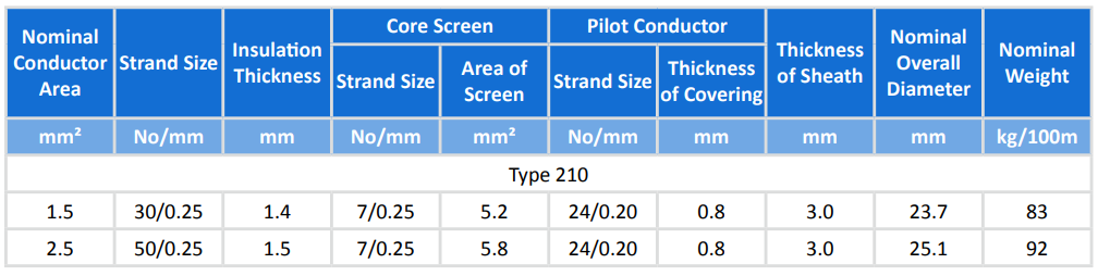
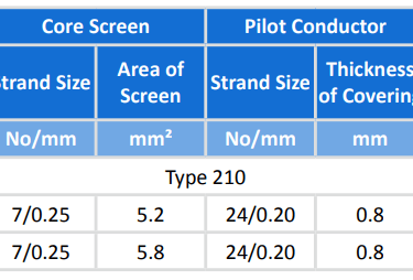
Current-carrying capability forms the foundation of any power cable's utility, and Type 210 cables excel in this critical area. Available in 1.5 square millimetre and 2.5 square millimetre conductor sizes, these cables can handle current loads of approximately 35 to 50 amperes under typical mining conditions. The 1.5 square millimetre variant suits lighter drilling equipment and applications where cable flexibility takes precedence over maximum current capacity. The 2.5 square millimetre option provides increased current-carrying capability for more demanding applications, such as larger drilling rigs or situations where longer cable runs might otherwise cause voltage drop issues.
The conductor sizing calculation for these cables takes into account not just the electrical load but also the thermal conditions prevalent in mining operations. Underground environments often suffer from poor ventilation, elevated ambient temperatures from machinery operation, and the heat generated by the drilling process itself. Type 210 cables incorporate thermal management principles in their design, using conductor sizes that maintain acceptable temperature rises even under these challenging conditions. The flexible stranded construction of the conductors also contributes to current-carrying capability by ensuring even current distribution across the conductor cross-section, preventing hot spots that could lead to insulation degradation.
Insulation performance represents perhaps the most critical aspect of Type 210 cable design. The EPR (ethylene-propylene rubber) insulation system provides exceptional resistance to the chemical and environmental challenges common in mining operations. This insulation maintains its electrical properties across a remarkable temperature range, from minus 30 degrees Celsius to plus 90 degrees Celsius, accommodating both the extreme cold of deep underground areas and the heat generated by intensive mining operations. The oil and ozone resistance of EPR insulation addresses the reality of mining environments, where hydraulic fluid leaks and chemical exposures are routine occurrences.
The flexibility characteristics of the insulation system deserve particular attention, as this directly impacts the cable's ability to withstand the continuous flexing required in mobile drilling applications. Traditional insulation materials become brittle under repeated flexing, leading to crack formation and eventual electrical failure. The EPR insulation in Type 210 cables maintains its flexibility throughout its service life, accommodating the millions of flex cycles that occur during normal drilling operations without degradation. This flexibility extends to low-temperature conditions, where many insulation materials become rigid and prone to cracking.
Standards compliance ensures that Type 210 cables meet the rigorous requirements established for Australian and New Zealand mining operations. Compliance with AS/NZS 1802 addresses the specific requirements for mining cables, ensuring that construction and performance meet established safety standards. AS/NZS 1125 covers the electrical performance requirements, while AS/NZS 3808 addresses the environmental and mechanical performance criteria. AS/NZS 5000.1 provides the overarching framework for electrical safety in mining applications. This comprehensive standards compliance ensures that Type 210 cables not only perform reliably but also meet the legal and safety requirements for mining operations throughout Australia and New Zealand.
Structural Design: Engineering Excellence in Every Layer
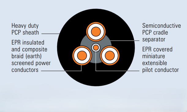
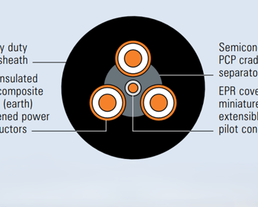
The internal construction of Type 210 cables represents a masterpiece of electrical engineering, where every layer serves multiple purposes in creating a cable that can withstand the extreme demands of mobile drilling operations. Understanding this construction helps explain why these cables perform so reliably in conditions that would quickly destroy conventional industrial cables.
The conductor core foundation consists of three flexible, tinned, annealed copper power cores, each engineered for maximum flexibility whilst maintaining excellent electrical conductivity. The use of tinned copper provides superior corrosion resistance compared to bare copper, essential in the humid, chemically aggressive environment of underground mining. The annealing process ensures that the copper remains flexible even after repeated bending cycles, preventing the work hardening that would eventually lead to conductor fracture. The stranded construction, using either 30 strands of 0.25 millimetre wire for the 1.5 square millimetre version or 50 strands for the 2.5 square millimetre variant, provides the flexibility necessary for continuous cable movement whilst maintaining excellent current-carrying capability.
Each power conductor receives individual insulation with EPR, creating three separately insulated cores within the cable. This individual insulation approach provides superior electrical performance compared to overall insulation systems, ensuring that each conductor operates independently whilst maintaining the flexibility required for mobile applications. The insulation thickness varies with conductor size, providing appropriate electrical breakdown strength whilst maintaining cable flexibility. For the 1.5 square millimetre conductors, the insulation thickness of 1.4 millimetres provides robust electrical protection, whilst the 1.5 millimetre thickness for 2.5 square millimetre conductors maintains the same dielectric strength with the larger conductor size.
The semiconductive elastomer screen surrounding each insulated conductor represents one of the most sophisticated aspects of Type 210 cable design. This screen serves multiple critical functions, including electric field distribution, capacitive coupling reduction, and electromagnetic interference suppression. By providing a controlled electrical path around each conductor, the screen ensures uniform electric field distribution, preventing the concentration of electrical stress that could lead to insulation breakdown. The elastomeric construction maintains flexibility whilst providing the electrical properties necessary for proper screen function, ensuring that this critical component continues operating effectively throughout the cable's service life.
The composite earth screen system combines electrical safety with mechanical protection in an innovative design approach. Tinned copper braiding provides the electrical path necessary for equipment grounding and fault current protection, whilst the interwoven polyester yarn adds mechanical strength and abrasion resistance. This composite construction creates a screen that maintains electrical continuity even when subject to the mechanical stresses of mobile drilling operations. The braided construction allows the screen to flex repeatedly without fatigue failure, whilst the polyester reinforcement prevents the copper braid from being damaged by abrasion or excessive tension.
The cradle separator, constructed from semiconductive PCP (polychloroprene), serves both mechanical and electrical functions within the cable. Mechanically, it provides support for the central pilot conductor whilst maintaining the overall cable geometry under flexing conditions. Electrically, its semiconductive properties contribute to the overall electrical field management within the cable, ensuring stable electrical performance under varying mechanical conditions. The PCP material provides excellent resistance to oil, ozone, and other chemical contaminants common in mining environments, ensuring long-term performance reliability.
The central extensible pilot conductor represents a unique feature that sets Type 210 cables apart from conventional industrial cables. This EPR-covered flexible stranded tinned copper conductor provides earth-continuity monitoring capability, allowing mining equipment to continuously monitor the integrity of the earth connection. This monitoring capability addresses a critical safety concern in mobile drilling operations, where earth connection integrity directly impacts operator safety. The extensible design ensures that the pilot conductor can accommodate the stretching and flexing that occurs during cable handling and operation without failure.
Sheath options provide the final layer of protection, with choices designed to match specific operational requirements. The standard heavy-duty PCP sheath provides excellent general-purpose protection against mechanical damage, chemical exposure, and environmental conditions. For more demanding applications, CPE (chlorinated polyethylene) or CSP (chlorosulfonated polyethylene) sheaths offer enhanced abrasion resistance and chemical protection. These premium sheath options are particularly valuable in applications where cables experience severe abrasion or exposure to aggressive chemicals, extending service life in the most challenging conditions.
The dimensional specifications of Type 210 cables reflect the careful balance between electrical performance, mechanical strength, and handling characteristics. The 1.5 square millimetre version, with its 23.7 millimetre overall diameter and 83 kilograms per 100 metres weight, provides excellent handling characteristics for applications where cable flexibility and weight are critical factors. The 2.5 square millimetre version, at 25.1 millimetres diameter and 92 kilograms per 100 metres, offers increased current-carrying capability with only modest increases in size and weight, making it suitable for more demanding electrical applications without creating handling difficulties.
Applications in Mobile Drilling Operations
The practical application of Type 210 cables in mobile drilling operations demonstrates how theoretical engineering excellence translates into real-world mining productivity. These cables serve as the critical link between power sources and mobile drilling equipment, operating in environments where reliability directly impacts both safety and operational efficiency. Understanding these applications provides insight into why the sophisticated design of Type 210 cables is not merely academic but absolutely essential for successful mining operations.
Cable reel systems represent the most common deployment method for Type 210 cables in mobile drilling operations. These systems mount either on drilling rigs themselves or on separate wheeled units that accompany mobile drilling equipment. The reel design must accommodate the continuous winding and unwinding that occurs as drilling equipment moves between work locations, whilst protecting the cable from damage during storage and handling. Type 210 cables excel in this application because their flexible construction tolerates the repeated bending cycles associated with reel operation, whilst their robust sheath protection prevents damage from contact with reel flanges and guide rollers.
The engineering of effective cable reel systems requires careful consideration of bend radius limitations, which directly impact cable service life. Type 210 cables specify minimum bend radii of six times the cable diameter, meaning that reel systems must incorporate appropriately sized drums to prevent cable damage. The 23.7 millimetre diameter of the 1.5 square millimetre cable requires a minimum bend radius of approximately 142 millimetres, whilst the 25.1 millimetre diameter of the 2.5 square millimetre version requires 151 millimetres. Properly designed reel systems exceed these minimums, providing operational margins that extend cable life and maintain electrical performance.
Drag line applications present even more demanding conditions for Type 210 cables, particularly when supporting handheld rock drills. In these applications, cables must withstand being dragged across rough rock surfaces, around sharp corners, and through areas where debris and moisture create additional hazards. The cable may be subjected to crushing forces when drilling equipment is positioned over it, abrasion from contact with rock surfaces, and tension forces when the cable becomes caught on obstacles or supports the weight of drilling equipment. The composite earth screen and heavy-duty sheath construction of Type 210 cables specifically address these challenges, providing mechanical protection that allows the cables to survive conditions that would quickly destroy conventional cables.
The operational characteristics that make Type 210 cables ideal for mobile drilling applications extend beyond mere mechanical ruggedness. The current-carrying capability of these cables matches well with the power requirements of modern drilling equipment, providing sufficient capacity for motor starting currents and sustained drilling loads without excessive voltage drop. The 35 to 50 ampere capacity covers the range of current demands from lightweight handheld drills to substantial track-mounted drilling rigs, allowing mining operations to standardise on a single cable type across multiple equipment types.
Flexibility remains paramount in mobile drilling applications, where cables must accommodate the complex movements of drilling equipment whilst maintaining electrical integrity. Drilling rigs frequently operate in confined spaces where cables must bend around obstacles, follow complex routing paths, and accommodate equipment movements in multiple directions simultaneously. The flexible conductor construction and EPR insulation system of Type 210 cables maintain electrical performance under these demanding conditions, preventing the electrical failures that could halt drilling operations.
The pilot conductor feature of Type 210 cables provides an additional layer of safety monitoring that proves invaluable in mobile drilling applications. This conductor allows continuous monitoring of earth connection integrity, providing early warning of earth system failures that could create shock hazards for operators. In handheld drilling applications, where operators are in direct contact with equipment, this monitoring capability can prevent accidents by alerting operators to earth system problems before they become dangerous. The extensible design of the pilot conductor ensures that this monitoring capability remains functional even under the mechanical stresses of mobile operation.
Temperature performance becomes particularly critical in mobile drilling applications, where cables may be stored in cold surface conditions and then deployed in the elevated temperatures of underground operations. The minus 30 to plus 90 degrees Celsius temperature range of Type 210 cables accommodates these extreme variations without performance degradation. The EPR insulation maintains its flexibility and electrical properties across this entire range, ensuring that cables perform consistently regardless of environmental temperature variations.
Chemical resistance plays an important role in mobile drilling applications, where cables may encounter hydraulic fluids, cutting oils, and other chemicals used in drilling operations. The oil and ozone resistance of the EPR insulation, combined with the chemical resistance of the PCP or optional CPE/CSP sheathing, provides protection against chemical degradation that could compromise cable performance. This chemical resistance extends cable service life and maintains electrical safety even in contaminated environments.

Frequently Asked Questions: Troubleshooting Common Field Issues
Field experience with Type 210 cables has identified several recurring issues that mining operations encounter, along with proven solutions that can restore cable performance or prevent problems from occurring. Understanding these common challenges and their solutions enables mining personnel to maximise cable performance and minimise operational disruptions.
Question: The pilot core appears to be broken, and we're not getting signal continuity. What should we do?
Answer: A broken pilot core indicates a significant mechanical failure within the cable that compromises the earth-continuity monitoring system. This failure typically results from excessive mechanical stress, sharp bend radius violations, or crushing damage to the cable. The immediate response should be to remove the affected cable from service and replace it with a known good cable to restore safe operation. Attempting to operate drilling equipment without pilot core continuity monitoring creates an unacceptable safety risk, as operators will not receive warning of earth system failures that could create shock hazards.
If immediate cable replacement is not possible, a temporary splice may restore pilot core continuity, but this should only be performed by qualified personnel using appropriate splice techniques and materials. The splice location must be protected from mechanical damage and environmental exposure, and the temporary repair should be replaced with a permanent solution as soon as practical. Proper grounding verification becomes even more critical when operating with spliced pilot cores, requiring additional earth continuity testing to ensure operator safety.
Question: We're seeing sheath cuts and excessive wear where the cable contacts rock surfaces during drilling operations. How can we prevent this damage?
Answer: Sheath damage from rock contact represents one of the most common failure modes in mobile drilling applications. The solution involves both cable selection and operational practices. Consider upgrading to Type 210 cables with CPE or CSP sheath options, which provide significantly enhanced abrasion resistance compared to standard PCP sheathing. These premium sheath materials can extend cable life by several times in high-abrasion environments.
Operational practices can further reduce abrasion damage. Install protective conduit or spiral cable guards in areas where cables routinely contact sharp rock surfaces. Use low-friction cable guides and rollers to redirect cable routing away from abrasive surfaces. Train operators to be conscious of cable positioning and to avoid dragging cables across sharp edges whenever possible. Regular inspection of cable routing can identify problematic contact points before they cause significant damage, allowing protective measures to be installed proactively.
Question: Our cable appears to be overheating under heavy drilling loads. What could be causing this, and how should we address it?
Answer: Cable overheating typically indicates that the current load exceeds the cable's capacity under the existing installation conditions. Begin by measuring the actual current draw of the drilling equipment and comparing it to the cable's rated capacity. Consider that the rated capacity assumes specific installation conditions, including ambient temperature, bundling with other cables, and airflow around the cable. Underground mining conditions often exceed these assumptions, reducing the cable's effective current-carrying capacity.
If the current load exceeds the cable's capacity, the solution is to upgrade to the 2.5 square millimetre version of Type 210 cable, which provides increased current-carrying capability. If overheating occurs even with appropriate cable sizing, investigate the installation conditions. Improve airflow around the cable by routing it away from heat sources and ensuring adequate ventilation. Avoid bundling power cables together, as this reduces the cooling capacity of each cable. Consider using cable spreaders or separators to maintain spacing between multiple cables in the same routing path.
Question: The cable insulation appears to be cracking in cold temperature conditions. How can we prevent this?
Answer: EPR insulation in Type 210 cables is rated for operation down to minus 30 degrees Celsius, which covers most mining applications. If cracking occurs within this temperature range, it typically indicates either defective cable or excessive mechanical stress combined with cold conditions. Cables stored in extremely cold surface conditions should be warmed gradually before deployment, allowing the insulation to regain its flexibility before subjecting it to bending forces.
For operations in conditions colder than minus 30 degrees Celsius, special low-temperature-rated cables may be necessary. Alternatively, cable heating systems can maintain cable temperature above the minimum rating during storage and initial deployment. Underground mining operations typically maintain temperatures well above the minimum rating due to geothermal effects and equipment heat generation, so cold temperature problems are most common during surface storage and initial cable deployment.
Question: We suspect moisture ingress is causing electrical faults. How should we address this?
Answer: Moisture ingress can cause immediate electrical failures and long-term insulation degradation. The first step is to de-energise the affected cable and drain any accumulated water from low points in the cable routing. Perform insulation resistance testing using a megohmmeter to quantify the extent of moisture contamination and identify the location of water ingress.
If testing indicates significant moisture contamination, the cable should be dried using appropriate techniques such as heat guns or warm air circulation, taking care not to exceed the cable's temperature rating. After drying, repeat the insulation resistance testing to verify that electrical performance has been restored. If drying does not restore adequate insulation resistance, the cable should be replaced, as moisture may have caused permanent insulation damage.
Prevention of moisture ingress requires attention to cable terminations, splices, and routing. Ensure that all cable terminations use appropriate weatherproof connectors and that splices are properly sealed. Route cables to avoid low points where water can accumulate, and provide drainage at unavoidable low points. Regular inspection of cable routing can identify areas where water accumulation might occur, allowing preventive measures to be implemented.
Question: We're experiencing earth shield malfunctions that could create shock hazards. What's the proper response?
Answer: Earth shield malfunctions represent a serious safety concern that requires immediate attention. Begin by de-energising the affected circuit and conducting a thorough inspection of the earth braid continuity throughout the cable length. Pay particular attention to areas where the cable has been subject to mechanical stress, as earth braid failures often occur at these locations.
The pilot conductor system in Type 210 cables provides continuous monitoring of earth system integrity, which should alert operators to earth shield problems before they become dangerous. If the pilot conductor indicates earth system failure, do not attempt to operate the equipment until the problem is resolved. Inspect the earth shield connections at both ends of the cable, ensuring that proper electrical contact exists between the cable earth screen and equipment grounding systems.
If earth shield damage is localised, it may be possible to restore continuity through proper splicing techniques, but this should only be performed by qualified personnel using appropriate materials and methods. More extensive earth shield damage requires cable replacement to ensure operator safety. Remember that the earth shield provides protection against both equipment faults and electromagnetic interference, so proper function is essential for both safety and equipment performance.
Question: We're seeing excessive abrasion damage where cables bend around pulleys and guides. How can we minimise this?
Answer: Abrasion damage at bend points typically results from inadequate bend radius, rough pulley surfaces, or improper cable support. Verify that all pulleys and cable guides provide bend radii of at least six times the cable diameter, with larger radii preferred for extended service life. Inspect pulley and guide surfaces for roughness, damage, or contamination that could increase abrasion.
Install proper cable lubrication systems at high-wear points, using lubricants compatible with the cable sheath material. Consider upgrading to larger diameter pulleys and guides to reduce the severity of cable bending. Use bearing-mounted pulleys rather than fixed guides wherever possible, as rotating pulleys reduce cable wear compared to stationary contact surfaces.
Training operators to avoid sharp cable bends during manual handling can significantly reduce abrasion damage. Establish minimum bend radius requirements for manual cable handling and provide tools such as cable rollers to maintain proper bend radii during cable installation and routing changes. Regular inspection of cable condition at bend points allows early identification of wear patterns, enabling corrective action before significant damage occurs.
Safety Protocols and Inspection Procedures
Establishing comprehensive safety protocols and inspection procedures for Type 210 cables is essential for maintaining both operational efficiency and worker safety in mobile drilling operations. These procedures must address the unique challenges of mining environments whilst ensuring that cable performance remains within acceptable parameters throughout the service life.
Daily visual inspections form the foundation of effective cable maintenance programs. These inspections should occur before each shift and focus on identifying obvious signs of cable damage, including cuts, cracks, kinks, and abrasion wear. Particular attention should be paid to areas where cables contact equipment or surfaces, bend around obstacles, or pass through tight spaces. Operators should look for signs of sheath discoloration that might indicate overheating, moisture ingress evidenced by water accumulation around cable terminations, and any deformation of the cable that might indicate internal damage.
The visual inspection process should include examination of cable terminations and connections, ensuring that all connections remain tight and free from corrosion or contamination. Inspect strain reliefs and cable glands for proper function, as these components play crucial roles in preventing cable damage at equipment interfaces. Document any anomalies discovered during visual inspections, as trending of minor damage can provide early warning of developing problems that might require proactive intervention.
Weekly electrical testing provides a more comprehensive assessment of cable condition and should include continuity testing of both power conductors and the pilot conductor system. This testing verifies that all electrical paths remain intact and capable of carrying their intended loads. Insulation resistance testing using a megohmmeter provides quantitative assessment of insulation condition, allowing detection of moisture ingress or insulation degradation before these problems cause failures.
The pilot conductor continuity test deserves particular attention, as this system provides the primary earth-continuity monitoring for mobile drilling equipment. Test both the continuity of the pilot conductor itself and its proper connection to equipment earth systems. Any interruption in pilot conductor continuity requires immediate investigation and correction before equipment operation resumes. Document all test results to establish baseline values and track changes over time that might indicate developing problems.
Monthly comprehensive inspections should include detailed mechanical examination of the entire cable length, focusing on areas that experience the greatest mechanical stress. These inspections may require partially disassembling cable routing systems to access normally hidden cable sections. Look for signs of internal damage that might not be visible during routine inspections, including conductor displacement within the cable, insulation compression, and earth screen damage.
Mechanical testing during monthly inspections should include verification that cable flexibility remains within specification limits. Cables that have become stiff or difficult to bend may have suffered internal damage that compromises their ability to withstand continued flexing. Test cable memory by coiling and uncoiling sections of cable, observing whether the cable returns to its original shape or retains permanent deformation that indicates damage.
Lifecycle management procedures should establish clear criteria for cable replacement based on age, usage hours, or condition assessment results. Manufacturer specifications typically provide guidance on expected service life under various operating conditions, but actual service life will depend on the specific conditions encountered in each mining operation. Establish replacement schedules that account for the criticality of each cable application, replacing cables in critical applications more frequently than those in less critical roles.
Environmental monitoring should track the conditions to which cables are exposed, including temperature extremes, chemical exposure, and mechanical stress levels. This information helps predict cable service life and optimize replacement schedules. Consider installing temperature monitoring devices in areas where cables are exposed to elevated temperatures, allowing proactive intervention when conditions exceed cable ratings.
Training programs for mining personnel should emphasise proper cable handling techniques, inspection procedures, and recognition of conditions that might damage cables. Operators should understand the importance of maintaining proper bend radii, avoiding sharp edges, and protecting cables from mechanical damage during equipment operation. Maintenance personnel should receive training in proper cable testing procedures, interpretation of test results, and criteria for determining when cable replacement is necessary.
Emergency response procedures should address cable failures that occur during operations, providing clear guidance for safely shutting down equipment, isolating damaged cables, and implementing temporary repairs when necessary. These procedures should emphasise safety as the primary concern, ensuring that personnel understand when it is safe to attempt repairs and when immediate evacuation or equipment shutdown is required.
Conclusion: The Critical Role of Type 210 Cables in Modern Mining
Type 210 1.1/1.1kV mining cables represent far more than simple electrical conductors; they embody the engineering sophistication necessary to support Australia's demanding mining operations. Through their carefully engineered construction, from the flexible tinned copper conductors to the protective composite earth screen, these cables provide the reliability foundation upon which modern mobile drilling operations depend. The integration of electrical power transmission with earth-continuity monitoring through the pilot conductor system demonstrates how thoughtful engineering can address multiple operational requirements within a single robust package.
The electrical performance characteristics of Type 210 cables, including their 1.1/1.1kV rating and 35 to 50 ampere current-carrying capacity, provide exactly the capability required for mobile drilling applications without the excess complexity or cost of overspecified alternatives. The EPR insulation system offers the chemical resistance, temperature performance, and flexibility necessary for the demanding environment of underground mining, whilst the standards compliance ensures that these cables meet the rigorous safety and performance requirements established for Australian mining operations.
Understanding the structural design principles behind Type 210 cables illuminates why these cables succeed where conventional industrial cables fail. Every layer, from the semiconductive elastomer screens to the composite earth conductor, serves specific functions that address the unique challenges of mobile drilling operations. The availability of enhanced sheath options, including CPE and CSP variants, allows mining operations to optimise cable selection for their specific environmental conditions, maximising service life and operational reliability.
The practical applications of Type 210 cables in mobile drilling operations demonstrate how engineering excellence translates into operational success. Whether powering handheld rock drills in confined spaces or supporting the complex movements of track-mounted drilling rigs, these cables provide the electrical infrastructure that enables Australia's mining industry to access mineral resources safely and efficiently. The cable reel systems and drag line applications that define mobile drilling operations depend absolutely on the reliability and durability that Type 210 cables provide.
The comprehensive troubleshooting guidance presented here reflects the real-world experience of mining operations throughout Australia, providing practical solutions to the most common cable-related challenges. From pilot conductor failures to moisture ingress problems, understanding these issues and their solutions enables mining personnel to maximise cable performance and minimise operational disruptions. The emphasis on safety protocols and inspection procedures ensures that Type 210 cables continue providing reliable service throughout their operational life whilst maintaining the safety standards essential for mining operations.
The safety and inspection protocols outlined here represent best practices developed through decades of mining experience, emphasising the critical importance of proactive maintenance in preventing cable failures that could compromise both safety and productivity. Daily visual inspections, weekly electrical testing, and monthly comprehensive examinations provide the systematic approach necessary to maintain cable performance in demanding mining environments. The lifecycle management principles ensure that cables are replaced before they reach the point of failure, maintaining operational reliability whilst optimising costs.
Type 210 mining cables will continue playing a crucial role as Australia's mining industry evolves to meet growing global demand for mineral resources. The engineering principles that make these cables successful in current applications provide a foundation for future developments, whether addressing new mining techniques, deeper operations, or more challenging environmental conditions. The proven reliability of Type 210 cables in existing applications provides confidence that these cables will continue supporting Australia's mining industry as it adapts to future challenges.
For mining operations seeking to optimise their electrical infrastructure, Type 210 cables offer a proven solution that balances performance, reliability, and cost-effectiveness. The comprehensive understanding provided here enables informed decisions about cable selection, installation practices, and maintenance procedures that will maximise the return on investment in cable infrastructure. By following the guidance presented here, mining operations can ensure that their Type 210 cables provide years of reliable service, supporting the productivity and safety that define successful mining operations.
The success of Australia's mining industry depends on countless components working together reliably under demanding conditions. Type 210 mining cables exemplify the engineering excellence that makes this success possible, providing the electrical infrastructure foundation that enables mobile drilling operations to access mineral resources safely and efficiently. Understanding these cables, from their sophisticated internal construction to their practical applications and maintenance requirements, represents essential knowledge for anyone involved in modern mining operations. Through proper selection, installation, and maintenance of Type 210 cables, Australia's mining industry can continue its tradition of technological leadership whilst maintaining the safety standards that protect the dedicated professionals who power our nation's mineral resource development.

