Type 241 Heavy-Duty Reeling Cable: Powering Australia's Underground Mining Fleet - From Shuttles to Boggers
Comprehensive guide to Type 241 1.1kV-11kV heavy-duty reeling cables for shuttle cars, boggers, and underground loaders. Australian mining standards, installation guidelines, and technical specifications.
6/16/202524 min read

Type 241 Heavy-Duty Reeling Cable: Powering Australia's Underground Mining Fleet - From Shuttles to Boggers
Introduction: The Backbone of Underground Power Distribution
Deep beneath the surface of Australia's mining operations, where the sun never shines and reliability means everything, a critical component quietly ensures that production never stops. The Type 241 heavy-duty reeling cable represents the lifeline that connects power to the mobile equipment that forms the backbone of underground mining operations. These cables, rated from 1.1 kV up to 11 kV, are specifically engineered to withstand the punishing conditions found in underground mines while maintaining consistent power delivery to shuttle cars, boggers, scoops, and other essential mining equipment.
Understanding the importance of reliable power supply in underground mining environments cannot be overstated. When equipment fails underground, the consequences extend far beyond simple downtime. Production stops, workers may be stranded, and the complex logistics of underground operations can be severely disrupted. This is why the selection and proper implementation of reeling cables becomes a critical engineering decision that affects every aspect of mining operations.
The Type 241 cable system represents decades of engineering evolution, incorporating lessons learned from countless underground installations across Australia, South Africa, and other major mining regions. These cables must simultaneously handle the mechanical stresses of constant reeling and unreeling while maintaining electrical integrity in environments characterized by dust, moisture, vibration, and temperature extremes that would quickly destroy conventional electrical cables.
Equipment Background: Understanding the Mechanical Context
To truly appreciate the role of Type 241 reeling cables, we must first understand the mechanical environment in which they operate. The underground mining ecosystem revolves around several key pieces of mobile equipment, each with its own unique power requirements and operational characteristics that directly influence cable design and selection.
Shuttle cars represent perhaps the most common application for reeling cables in underground coal mining operations. These battery-electric vehicles serve as the critical link between the coal face and the main conveyor system. A typical shuttle car operates on rubber tires and can carry loads ranging from 10 to 20 tonnes of coal per trip. The power requirements for these machines are substantial, as they must provide enough torque to accelerate heavy loads from a standstill while navigating the confined spaces and steep gradients common in underground mines. The reeling cable system must be capable of delivering consistent power throughout the shuttle's operational cycle, which can involve rapid acceleration, sustained hauling, and frequent stops and starts.
Underground loaders, commonly referred to as "boggers" in Australian mining parlance, represent another significant application for heavy-duty reeling cables. These load-haul-dump (LHD) machines are typically more powerful than shuttle cars and are used for a broader range of materials handling tasks. A bogger might be equipped with a diesel engine for propulsion combined with electric motors for hydraulic systems, or it might be entirely electric. The power requirements can be quite variable, with peak demands occurring during the loading cycle when hydraulic systems are operating at maximum capacity to lift and maneuver heavy buckets of ore or waste rock.
The term "scoop" is used more broadly across different mining regions to describe various types of underground loading equipment. These machines share common characteristics with boggers but may have different configurations depending on the specific mining method and local preferences. Regardless of the specific terminology used, all of these machines share the common requirement for reliable mobile power delivery through reeling cable systems.
The working conditions that these machines and their associated cables must endure are among the most challenging found in any industrial application. Underground mines are characterized by high humidity, corrosive atmospheres, abrasive dust, and constant vibration. Temperatures can vary significantly, from near-freezing conditions in some deep mines to extremely hot conditions in others, particularly those with high geothermal gradients. The mechanical stresses imposed on cables include not only the normal flexing associated with reeling and unreeling but also the shock loads that occur when equipment encounters obstacles or uneven surfaces.


Electrical Parameters: The Technical Foundation
The electrical characteristics of Type 241 cables are carefully engineered to meet the demanding requirements of underground mining applications while maintaining compliance with rigorous Australian and international standards. The voltage rating range from 1.1 kV to 11 kV provides flexibility to accommodate different mining operations, from smaller shuttle car applications to major feeder systems supplying continuous miners and other high-power equipment.
The voltage selection process requires careful consideration of several factors. Lower voltage systems, typically operating at 1.1 kV, are commonly used for shuttle car applications where the power requirements are moderate and the cable runs are relatively short. The advantage of lower voltage systems lies in their simpler installation requirements and reduced safety hazards during maintenance operations. However, as power requirements increase or cable runs become longer, higher voltage systems become necessary to maintain acceptable voltage drop levels and improve overall system efficiency.
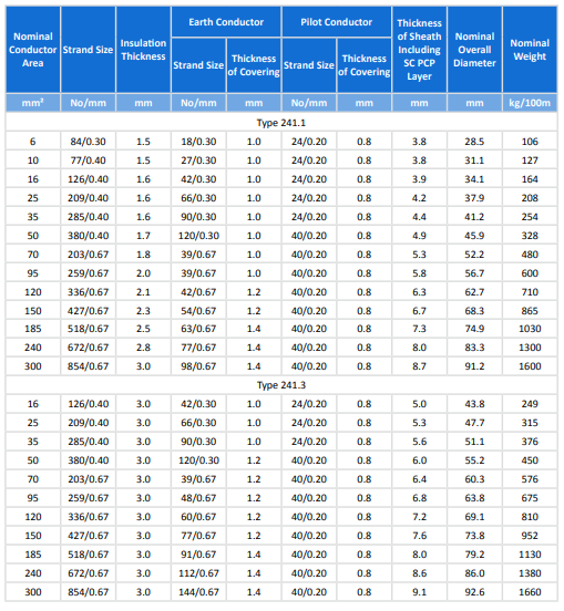
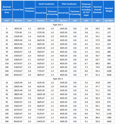
The conductor cross-sectional areas available in the Type 241 series range from 6 mm² up to 300 mm², providing current-carrying capacities that can accommodate virtually any underground mining application. The relationship between conductor size and current-carrying capacity is not linear, as larger conductors benefit from improved heat dissipation characteristics and lower resistance per unit length. This relationship becomes particularly important in underground applications where ambient temperatures may be elevated and ventilation is limited.
The insulation system employed in Type 241 cables centers around ethylene propylene rubber (EPR), a material specifically chosen for its excellent electrical properties and resistance to the harsh conditions found in underground mines. EPR insulation provides superior performance across a wide temperature range and maintains its dielectric strength even when exposed to moisture and mechanical stress. The insulation thickness varies according to the voltage rating, with higher voltage cables requiring proportionally thicker insulation to maintain the required dielectric strength and safety margins.
The semiconductive screening system employed in Type 241 cables represents a critical safety feature that is often overlooked by those unfamiliar with underground mining electrical systems. The conductor screen, formed from a semiconductive compound, ensures uniform electric field distribution around the conductor, preventing the formation of voltage concentrations that could lead to insulation breakdown. The insulation screen performs a similar function on the outer surface of the insulation, providing a defined equipotential surface that enhances the overall electrical integrity of the system.
Compliance with Australian and New Zealand standards represents more than just a regulatory requirement; it ensures that cables meet the proven safety and performance criteria developed through decades of mining experience. AS/NZS 1802:2003 specifically addresses reeling and trailing cables used in mining applications, while AS/NZS 1125, 3808, and 5000.1 provide additional requirements for conductors, insulation systems, and general cable construction. These standards incorporate lessons learned from mining operations worldwide and provide the foundation for safe and reliable electrical systems in underground environments.
Product Construction and Structure: Engineering for Extreme Conditions
The construction of Type 241 cables represents a masterpiece of engineering optimization, with each layer and component carefully designed to contribute to the overall performance and reliability of the system. Understanding this construction is essential for proper selection, installation, and maintenance of these critical components.
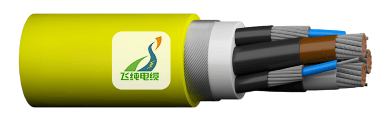
The core of the Type 241 cable system consists of three flexible stranded tinned copper conductors. The use of tinned copper is not merely a cost consideration but a carefully engineered choice that provides superior corrosion resistance in underground environments where moisture and chemical exposure are constant threats. The stranding pattern is optimized to provide maximum flexibility while maintaining structural integrity under the constant flexing associated with reeling operations. The individual conductor strands are carefully sized and arranged to minimize skin effect losses while maximizing the cable's ability to withstand repeated bending cycles.
Surrounding each conductor is a semiconductive conductor screen that serves multiple critical functions. This screen ensures uniform electric field distribution around the conductor, preventing the formation of stress concentrations that could lead to premature insulation failure. In underground mining applications, where cables may be subjected to physical damage from falling rocks or equipment contact, this screening system provides an additional margin of safety by ensuring that any partial damage to the insulation does not immediately result in catastrophic failure.
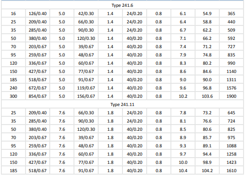
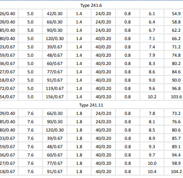
The insulation system itself represents the heart of the cable's electrical performance. EPR insulation is applied to each conductor in carefully controlled thicknesses that vary according to the voltage rating of the specific cable variant. Type 241.1 cables, designed for lower voltage applications, feature insulation thicknesses ranging from 1.5 mm to 3.0 mm depending on conductor size. Higher voltage variants such as Type 241.11 require significantly thicker insulation, with thicknesses reaching 7.6 mm for the highest voltage applications.
The insulation screen, formed from a semiconductive elastomer, provides the outer boundary of the electrical system for each conductor. This screen is critical for maintaining the integrity of the electric field distribution and provides a defined reference point for the cable's electrical characteristics. The quality and consistency of this screen directly impact the cable's ability to withstand electrical stress over its operational lifetime.
Between the three insulated conductors lies the cradle separator, formed from semiconductive polychloroprene (PCP). This component serves both mechanical and electrical functions, maintaining proper spacing between conductors while providing a degree of electrical shielding. The cradle separator also contributes to the overall mechanical integrity of the cable, helping to maintain the circular cross-section under the stresses associated with reeling operations.
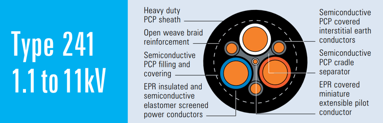
The overall core screen represents one of the most critical safety features of the Type 241 design. This screen, formed from semiconductive PCP filling and covering materials, completely encloses the three power conductors and provides a continuous earth reference throughout the length of the cable. This screen serves as the primary protection against electric shock in the event that the outer sheath is damaged, ensuring that any object breaching the sheath will make contact with the earthed screen before reaching the power conductors.
Embedded within the overall core screen are three interstitial earth conductors, each consisting of flexible stranded tinned copper covered with semiconductive PCP. These conductors provide a low-resistance path to earth and serve as the primary means of bonding the overall screen to the electrical system earth. The sizing of these earth conductors is carefully calculated to ensure they can safely carry fault currents that might occur in the event of insulation failure.
At the center of the cable assembly lies the central extensible pilot conductor, a feature that distinguishes reeling cables from their fixed installation counterparts. This pilot conductor, consisting of EPR-covered flexible stranded tinned copper, serves multiple functions in the overall system. It can be used for communication between the mobile equipment and fixed control systems, for monitoring cable integrity, or for providing control signals to equipment systems. The extensible nature of this conductor allows it to accommodate the additional length requirements that occur as the cable is reeled and unreeled.
The textile reinforcement layer, typically formed from an open-weave braid, provides mechanical protection for the internal cable components while maintaining flexibility. This reinforcement is particularly important in mining applications where cables may be subjected to abrasion from contact with rough surfaces or debris. The open-weave design ensures that the reinforcement does not significantly impact the cable's flexibility while still providing meaningful mechanical protection.
The outermost component of the cable assembly is the heavy-duty PCP sheath, engineered to provide protection against the harsh conditions encountered in underground mining environments. This sheath must simultaneously provide protection against abrasion, cutting, chemical attack, and moisture ingress while maintaining sufficient flexibility to accommodate the constant flexing associated with reeling operations. The thickness of this sheath varies according to the overall size of the cable, with larger cables requiring proportionally thicker sheaths to maintain mechanical integrity.

Installation Guidelines and Best Practices: Ensuring Long-Term Reliability
The installation of Type 241 reeling cables requires careful attention to numerous factors that can significantly impact long-term reliability and performance. Unlike fixed cables, reeling cables must be installed with consideration for the dynamic stresses they will experience throughout their operational lifetime. This section explores the critical aspects of installation that determine whether a cable system will provide years of reliable service or suffer premature failure.
The selection and installation of reel drums represents perhaps the most critical aspect of reeling cable installation. The drum diameter must be carefully chosen to ensure that the minimum bend radius of the cable is never exceeded, even under the most extreme operating conditions. As a general rule, the drum diameter should be at least 20 times the overall cable diameter, though larger ratios are preferred for applications involving frequent reeling cycles. The drum surface must be smooth and free from sharp edges or protrusions that could damage the cable sheath during operation.
Proper cable routing from the drum to the equipment requires careful consideration of the path that the cable will follow as it is reeled and unreeled. The cable should be guided in a smooth curve that avoids sharp bends or contact with fixed objects. Guide rollers or sheaves should be used where necessary to maintain proper cable geometry, and these components must be sized appropriately to avoid exceeding the cable's minimum bend radius. The material and surface finish of guide components are also important, as they must not cause abrasion or damage to the cable sheath.
The tension applied to the cable during reeling operations must be carefully controlled to prevent damage to the internal components while ensuring proper winding on the drum. Excessive tension can cause deformation of the conductors or damage to the insulation system, while insufficient tension may result in loose winding that can lead to cable damage when subsequent layers are wound over it. Modern reeling systems often incorporate tension monitoring and control systems to maintain optimal conditions throughout the reeling cycle.
Connections between the reeling cable and both the power source and the mobile equipment represent critical points in the system that require special attention during installation. These connections must be designed to accommodate the mechanical stresses associated with cable movement while maintaining excellent electrical contact. The connection hardware must be suitable for the harsh underground environment and must provide effective sealing against moisture ingress. The earth screen of the cable must be properly bonded at both ends to ensure effective earth fault protection.
The earthing procedures for Type 241 cables go beyond simple connection of the earth conductors. The overall semiconductive screen must be bonded to the electrical system earth at appropriate points to ensure that it can effectively perform its protective function. This bonding must be maintained throughout the installation and must be verified during commissioning and periodic maintenance activities. The integrity of the earth system is critical for both personnel safety and equipment protection.
Environmental considerations during installation include protection of the cable from physical damage during the installation process and ensuring that the final installation provides adequate protection against ongoing environmental hazards. The installation route should avoid areas where the cable might be exposed to excessive heat, corrosive chemicals, or mechanical damage from mobile equipment. Where such exposure cannot be avoided, additional protective measures such as cable guards or specialized routing may be required.
Mining Slang in Operation: Understanding the Language of Underground Operations
The terminology used in underground mining operations reflects the unique culture and practical requirements of this specialized industry. Understanding this language is essential for anyone working with reeling cables in mining applications, as it provides insight into both the equipment and the operational context in which these cables must function.
The term "shuttle" has become synonymous with the battery-electric vehicles that transport coal from the face to the main conveyor system in underground coal mines. These machines, properly known as shuttle cars, represent one of the most common applications for Type 241 reeling cables. A typical shuttle car operation involves the machine receiving coal from a continuous miner, then traveling along predetermined routes to discharge points where the coal is transferred to the main conveyor system. The power requirements during this cycle vary significantly, with peak demands occurring during acceleration and climbing grades. The reeling cable system must be capable of delivering consistent power throughout this operational cycle while accommodating the constant motion of the shuttle car.
In Australian mining operations, the term "bogger" is universally understood to refer to load-haul-dump (LHD) equipment used for materials handling in underground mines. This terminology has its roots in the early days of mechanized mining when these machines were used to "bog" or extract ore from stopes and transport it to underground crushers or ore passes. Modern boggers are sophisticated pieces of equipment that may be diesel-powered, electric, or hybrid, with power requirements that can exceed those of shuttle cars due to the hydraulic systems required for loading and dumping operations. The reeling cables serving boggers must be capable of handling the high instantaneous power demands associated with hydraulic operations while providing consistent power for propulsion.
The term "scoop" is used more broadly across different mining regions and can refer to various types of underground loading equipment. In some operations, scoop specifically refers to smaller loading machines used for maintenance activities or material handling in confined spaces. In others, it may be used interchangeably with bogger or LHD. Regardless of the specific terminology, all of these machines share common characteristics in terms of their power requirements and the need for reliable mobile power delivery through reeling cable systems.
Real-world usage examples from mines across Australia, South Africa, and China demonstrate the global applicability of these terminologies and the universal challenges associated with powering mobile underground equipment. In Australian coal mines, shuttle cars operating on 1000-volt systems typically utilize Type 241.1 cables with conductor sizes ranging from 70 mm² to 150 mm², depending on the specific power requirements and cable length. South African gold mines often employ boggers powered by higher voltage systems, requiring Type 241.3 or 241.6 cables to accommodate the longer cable runs and higher power requirements associated with deep mining operations.
Chinese mining operations, with their emphasis on high-volume production, often employ larger equipment with correspondingly higher power requirements. In these applications, Type 241.11 cables operating at 11 kV may be required to supply power to large continuous miners or other high-power equipment. The specific terminology used in Chinese mines may differ from that used in English-speaking countries, but the fundamental requirements for reliable mobile power delivery remain consistent.
Understanding the operational context behind these terms is crucial for proper cable selection and installation. A shuttle car operation typically involves relatively predictable power demands and cable routing, making it suitable for standard reeling cable installations. Bogger operations, however, may involve more variable power demands and less predictable cable routing, potentially requiring specialized cable management systems or alternative installation approaches.
The environmental conditions associated with different types of mining operations also influence cable selection and installation requirements. Coal mining operations typically involve relatively dry conditions with moderate temperatures, making them suitable for standard PCP sheath materials. Hard rock mining operations, particularly those involving sulfide ores, may present more challenging chemical environments that require specialized sheath materials or additional protective measures.
Typical Applications in Mines: Powering the Underground Fleet
The versatility of Type 241 reeling cables makes them suitable for a wide range of underground mining applications, each with its own specific requirements and challenges. Understanding these applications provides insight into the engineering decisions that drive cable selection and installation practices.
Power supply for shuttle car traction and drive motors represents one of the most common applications for Type 241 cables. These applications typically involve relatively moderate power requirements, with cable ratings ranging from 35 mm² to 150 mm² depending on the size and power requirements of the specific shuttle car. The operational cycle of a shuttle car is relatively predictable, with defined routes and consistent power demands that make it suitable for standard reeling cable installations. The key considerations for shuttle car applications include ensuring adequate current-carrying capacity for the traction motors, maintaining acceptable voltage drop levels over the required cable length, and providing reliable earth fault protection through proper bonding of the cable screen system.
Feeder applications for continuous miners represent a more demanding application that often requires larger cable sizes and higher voltage ratings. Continuous miners are high-power machines that combine cutting, loading, and conveying functions in a single unit. The power requirements for these machines can be substantial, often requiring Type 241.3 or 241.6 cables with conductor sizes ranging from 95 mm² to 240 mm² or larger. The intermittent nature of continuous miner operations, with high power demands during cutting cycles followed by lower power requirements during repositioning, places unique stresses on the cable system that must be considered during selection and installation.
Pump systems in underground mines present another important application for Type 241 reeling cables. Mine pumping systems must operate continuously and reliably to prevent flooding of underground workings. The power requirements for pump systems can vary significantly depending on the size and depth of the mine, with larger systems requiring substantial cable installations. The critical nature of pumping systems often dictates the use of redundant cable installations to ensure continued operation even in the event of cable failure.
Control panel and auxiliary system applications represent a growing area of use for smaller Type 241 cables. Modern mining operations rely heavily on sophisticated control and monitoring systems that require reliable power and communication connections. These applications often utilize smaller cable sizes, typically in the 6 mm² to 35 mm² range, but may require specialized configurations to accommodate both power and communication requirements.
The comparison between static and reeling cable applications highlights the unique advantages and challenges associated with each approach. Static cable installations, while simpler and less expensive initially, limit the mobility of equipment and may require extensive cable infrastructure to serve mobile equipment. Reeling cable systems, while more complex and expensive, provide the flexibility required for modern mining operations while reducing the overall cable infrastructure requirements.
The selection between different voltage ratings within the Type 241 series depends on several factors including power requirements, cable length, and system compatibility. Lower voltage systems (1.1 kV to 3.3 kV) are typically used for shorter cable runs and moderate power applications, while higher voltage systems (6.6 kV to 11 kV) are required for longer cable runs or higher power applications where voltage drop considerations become critical.
Potential Underground Challenges and FAQ: Solving Real-World Problems
The harsh and demanding environment of underground mining presents numerous challenges that can affect the performance and reliability of reeling cable systems. Understanding these challenges and their solutions is essential for maintaining reliable operations and maximizing the service life of cable installations. The following frequently asked questions address the most common issues encountered in underground mining applications.
Question 1: Can Type 241 cables withstand exposure to belt spray and abrasive spillage commonly found near conveyor systems?
The heavy-duty PCP sheath used in Type 241 cables is specifically engineered to resist abrasion and provide protection against moisture and chemical exposure. The sheath material is formulated to maintain its protective properties even when exposed to the coal dust, water sprays, and chemical additives commonly used in underground mining operations. However, this protection is not unlimited, and regular inspection of cables operating in these environments is essential to identify early signs of sheath degradation before it progresses to the point where internal cable components are at risk.
The inspection process should focus on areas where the cable may contact conveyor structures, guide rollers, or other fixed equipment. Visual inspection can identify obvious signs of wear such as cuts, gouges, or excessive flattening of the cable cross-section. More subtle forms of degradation, such as chemical attack or gradual abrasion, may require more detailed inspection techniques including measurement of sheath thickness at critical points.
When cables must operate in particularly harsh environments, additional protective measures may be warranted. These can include the use of cable guards or protective conduits in areas of high abrasion risk, modification of cable routing to avoid the most severe exposure, or more frequent inspection and replacement schedules to ensure that cables are replaced before critical degradation occurs.
Question 2: How can bending fatigue on the reel head be minimized to prevent premature cable failure?
Bending fatigue represents one of the most common failure modes for reeling cables, particularly at the point where the cable leaves the reel drum. This area experiences the most severe and repetitive bending stresses, making it the most likely location for fatigue-related failures. The key to minimizing bending fatigue lies in ensuring that the minimum bend radius is never exceeded and that the cable path is optimized to distribute bending stresses as evenly as possible.
The reel drum diameter should be selected to provide a bend radius that is significantly larger than the minimum specified for the cable. While the minimum bend radius provides a safety threshold below which immediate damage may occur, operating closer to this limit will result in reduced service life due to accumulated fatigue damage. A general recommendation is to use a drum diameter that provides a bend radius at least 25 to 30 times the overall cable diameter for applications involving frequent reeling cycles.
The use of guided rollers or fairleads can help to control the cable path and reduce localized bending stresses. These components should be sized appropriately and positioned to provide smooth transitions between straight and curved sections of the cable path. The material and surface finish of these components must be compatible with the cable sheath to avoid abrasion or other forms of mechanical damage.
Regular inspection of the cable in the area near the reel head is essential for early detection of fatigue-related damage. This inspection should look for signs of conductor distortion, insulation cracking, or sheath damage that might indicate developing fatigue problems. When such problems are identified, the cable routing should be evaluated and modified if necessary to reduce the severity of bending stresses.
Question 3: Why is proper earthing of the cable sheath screen critical, and how should it be implemented?
The overall semiconductive screen in Type 241 cables serves as the primary protection against electric shock in the event that the outer sheath is damaged. This screen ensures that any object breaching the sheath will make contact with an earthed conductor before reaching the power conductors. However, this protection is only effective if the screen is properly bonded to the electrical system earth at both ends of the cable.
The earthing connection must provide a low-resistance path that is capable of carrying the full fault current that might flow in the event of an insulation failure. This requires both adequate conductor size and reliable connection techniques that will maintain their integrity throughout the service life of the installation. The earth conductors embedded in the cable are specifically sized to carry these fault currents, but the connections to the system earth must be designed and installed with equal care.
The earthing system must be bonded at both the supply end and the equipment end of the cable. At the supply end, the earth conductors should be connected to the substation earthing system through appropriate switchgear earthing terminals. At the equipment end, the earth conductors should be connected to the equipment frame and control system earth. The integrity of these connections should be verified during installation and checked periodically as part of routine maintenance activities.
In addition to providing personnel protection, proper earthing of the screen system is essential for reliable operation of earth fault protection systems. These systems depend on the flow of fault current through the earth circuit to detect and isolate faulted cables or equipment. If the earth circuit is not properly maintained, earth faults may not be detected reliably, potentially leading to extended exposure to dangerous conditions.
Question 4: What should be done when cable tracking errors occur or the pilot conductor fails?
The central extensible pilot conductor in Type 241 cables serves multiple functions including communication, control signaling, and cable integrity monitoring. When problems occur with the pilot conductor, they can affect not only communication systems but also safety monitoring functions that depend on pilot conductor continuity.
Cable tracking errors, where the system loses track of cable position or length, can often be traced to problems with the pilot conductor or its associated monitoring equipment. The first step in troubleshooting these problems is to verify the continuity and integrity of the pilot conductor throughout its length. This can be accomplished using standard electrical testing techniques, though care must be taken to ensure that testing does not interfere with other systems that may be connected to the pilot conductor.
If pilot conductor damage is identified, the location and extent of the damage must be determined to evaluate repair options. Minor damage near the cable ends may be repairable through replacement of cable terminations, while damage in the middle of the cable length may require replacement of the entire cable. The extensible nature of the pilot conductor makes it particularly susceptible to damage from excessive tension or improper installation, so these factors should be evaluated when pilot conductor problems are identified.
Preventive measures for pilot conductor reliability include ensuring that the conductor is not subjected to excessive tension during installation or operation, protecting the conductor terminations from mechanical damage and moisture ingress, and including pilot conductor continuity checks in routine maintenance procedures. Many modern reeling systems incorporate continuous monitoring of pilot conductor integrity, providing early warning of developing problems before they result in system failures.
Question 5: How do thermal considerations affect cable selection and installation in high-humidity or high-temperature mining environments?
The thermal environment in underground mines can vary significantly depending on factors such as depth, geological conditions, ventilation systems, and equipment heat generation. These thermal conditions directly affect the current-carrying capacity of cables and must be carefully considered during cable selection and installation.
EPR insulation used in Type 241 cables is rated for continuous operation at temperatures up to 90°C, providing excellent thermal stability under normal mining conditions. However, the actual operating temperature of the cable depends not only on the ambient temperature but also on the heat generated by current flow through the conductors and the ability of the installation to dissipate this heat.
In high-temperature environments, cable derating may be necessary to ensure that the conductor temperature does not exceed safe limits. This derating is typically accomplished by reducing the allowable current or by using larger conductor sizes to reduce the heat generation per unit length. The specific derating factors depend on the ambient temperature, installation conditions, and grouping of multiple cables.
High humidity environments present additional challenges related to moisture ingress and electrical tracking. While the PCP sheath provides good moisture resistance, prolonged exposure to high humidity conditions can eventually lead to moisture penetration, particularly if the sheath is damaged. Regular inspection for signs of moisture ingress is essential in these environments, and additional protective measures such as improved drainage or ventilation may be warranted.
Ventilation around cable installations can significantly improve thermal performance by enhancing heat dissipation. In confined spaces where natural ventilation is limited, forced ventilation may be necessary to maintain acceptable operating temperatures. The ventilation system design should consider not only the heat generated by cables but also the heat from adjacent equipment and other sources.
Question 6: How should the voltage rating be selected when choosing between 1.1 kV and 11 kV systems?
The selection of voltage rating for Type 241 cables involves balancing several factors including power requirements, cable length, system compatibility, safety considerations, and economic factors. Understanding these trade-offs is essential for making informed decisions about cable specifications.
Lower voltage systems, typically operating at 1.1 kV to 3.3 kV, offer several advantages including simpler installation requirements, reduced safety hazards during maintenance, and lower equipment costs for switchgear and protection systems. These systems are well-suited for applications with moderate power requirements and relatively short cable runs, such as shuttle car operations or small equipment installations.
Higher voltage systems, operating at 6.6 kV to 11 kV, become necessary when power requirements are high or when cable runs are long enough that voltage drop becomes a limiting factor. The relationship between voltage and power transmission capacity is not linear; doubling the voltage can increase the power transmission capacity by a factor of four for the same conductor size and acceptable voltage drop. This makes higher voltage systems much more efficient for high-power applications.
The voltage drop calculation is critical for determining the minimum voltage rating required for a given application. Voltage drop depends on the current flow, conductor resistance, and cable length. As cable length increases or power requirements increase, the voltage drop increases proportionally. When voltage drop exceeds acceptable limits (typically 5% to 10% depending on the application), a higher voltage system becomes necessary.
System compatibility is another important consideration, as the cable voltage rating must match the voltage rating of the power source and connected equipment. In many cases, the voltage rating is predetermined by existing infrastructure, limiting the options available for cable selection. However, in new installations or major renovations, there may be flexibility to optimize the system voltage for the specific application requirements.
Safety considerations also influence voltage rating selection. Higher voltage systems require more sophisticated safety procedures and equipment, and the consequences of electrical faults are generally more severe. The training and experience of maintenance personnel must be considered when selecting voltage ratings, as higher voltage systems require specialized knowledge and equipment for safe maintenance.
Summary and Take-Home Points: Building Reliable Underground Power Systems
The successful implementation of Type 241 heavy-duty reeling cables in underground mining applications requires a comprehensive understanding of the mechanical, electrical, and environmental factors that influence their performance. These cables represent a critical component in the underground mining infrastructure, providing the reliable power delivery that modern mining operations depend on.
The key strengths of Type 241 cables lie in their carefully engineered construction that balances flexibility with mechanical robustness. The use of flexible stranded tinned copper conductors provides excellent electrical performance while maintaining the flexibility required for reeling applications. The comprehensive screening system, including both conductor screens and the overall core screen, provides multiple layers of electrical protection that are essential for safe operation in underground environments.
The mechanical robustness of Type 241 cables is achieved through the use of heavy-duty PCP sheath materials and reinforcement systems that can withstand the abrasion, impact, and environmental exposure common in underground mining. The cradle separator and overall core screen provide structural support while maintaining the electrical integrity of the system.
Proper installation represents perhaps the most critical factor in achieving reliable long-term performance from reeling cable systems. The selection of appropriate reel drums, proper cable routing, controlled tension during installation, and reliable connection techniques all contribute to system reliability. The importance of following manufacturer specifications and industry best practices cannot be overstated, as shortcuts during installation frequently lead to premature failures and costly downtime.
Maintenance of reeling cable systems requires ongoing attention to several key areas including regular inspection for mechanical damage, verification of electrical integrity, and monitoring of earth system continuity. The harsh underground environment means that gradual degradation is inevitable, making regular inspection and preventive maintenance essential for maximizing service life and preventing unexpected failures.
The evolution of mining terminology and slang reflects the practical experience of generations of miners and engineers who have worked to develop reliable underground power systems. Understanding this terminology provides insight into both the equipment and the operational context that drives the requirements for reeling cable systems. Whether referred to as shuttles, boggers, or scoops, these machines all share the common requirement for reliable mobile power delivery through carefully engineered cable systems.
The future of underground mining will likely bring new challenges and requirements for reeling cable systems, including higher power densities, more sophisticated control and monitoring systems, and more stringent environmental and safety requirements. The Type 241 cable design provides a solid foundation that can be adapted and evolved to meet these future challenges while maintaining the reliability and performance that current mining operations depend on.
Understanding the potential challenges and solutions associated with reeling cable systems enables mining engineers and maintenance personnel to make informed decisions about cable selection, installation, and maintenance practices. The frequently asked questions addressed in this article represent real-world problems that have been encountered and solved in mining operations worldwide, providing valuable guidance for avoiding similar problems in future installations.
The investment in proper cable selection, installation, and maintenance represents a small fraction of the total cost of underground mining operations, but the impact of cable failures on production and safety can be enormous. The comprehensive approach to reeling cable systems outlined in this article provides the foundation for achieving reliable long-term performance that justifies this investment and supports the overall success of underground mining operations.
References and Standards
The technical specifications and installation practices described in this article are based on Australian and New Zealand standards that have been developed through decades of mining experience and international collaboration. AS/NZS 1802:2003 provides comprehensive requirements for reeling and trailing cables used in mining applications, while AS/NZS 1125, 3808, and 5000.1 address specific aspects of conductor design, insulation systems, and general cable construction.
These standards represent the collective experience of mining engineers, cable manufacturers, and safety professionals from around the world and provide proven guidelines for achieving safe and reliable underground power systems. Compliance with these standards should be considered the minimum requirement for any mining cable installation, with additional measures implemented as necessary to address specific site conditions or operational requirements.
The ongoing evolution of these standards reflects the continuing development of mining technology and the lessons learned from operational experience worldwide. Mining professionals should stay current with standard revisions and industry best practices to ensure that their installations continue to represent the state of the art in underground power system design and implementation.

