Type 275 1.1/1.1KV Mining Cable in Shuttle Cars and Loaders
omprehensive guide to Type 275 1.1/1.1KV mining cable for shuttle cars, boggers, and scoops in Australian underground mining operations. Learn electrical specs, installation standards, and troubleshooting tips.
6/16/202526 min read
Type 275 1.1/1.1KV Mining Cable in Shuttle Cars and Loaders
Introduction
Deep beneath the earth's surface, where sunlight never penetrates and the air grows thick with dust, a complex network of machinery works tirelessly to extract the minerals that power our modern world. In these subterranean environments, every piece of equipment relies on a steady flow of electrical power to function safely and efficiently. The harsh conditions underground – from crushing rocks and corrosive chemicals to extreme temperatures and constant vibration – demand electrical infrastructure that can withstand punishment that would destroy ordinary cables in minutes.
Underground mining operations represent some of the most challenging electrical environments on Earth. The machinery must operate in confined spaces where a single electrical failure can mean the difference between a productive shift and a catastrophic accident. Water seepage, chemical exposure, mechanical stress, and the constant flexing of cables as machines move through narrow tunnels all combine to create conditions that push electrical systems to their absolute limits.
At the heart of this demanding environment lies the Type 275 1.1/1.1KV mining cable, a specialised power distribution solution designed specifically for the unique challenges of underground mining. This cable serves as the electrical lifeline for some of the most critical pieces of mining equipment, including shuttle cars, underground loaders, and pumping systems. Understanding how this cable works, why it's constructed the way it is, and how to use it properly can mean the difference between smooth operations and costly downtime in the depths of a mine.
The Type 275 cable represents decades of engineering evolution, incorporating lessons learned from countless mining operations across Australia and around the world. Its design philosophy centres on three core principles: flexibility to handle constant movement, durability to withstand harsh conditions, and safety to protect both equipment and personnel in environments where rescue can be extraordinarily difficult.
Mining Machinery Overview
To truly understand why the Type 275 cable is engineered the way it is, we need to first examine the machinery it powers and the unique challenges these machines face in underground environments. The mining industry has developed its own vocabulary over the decades, with terms like "shuttle," "bogger," and "scoop" becoming standard parlance in operations from the Hunter Valley coal mines to the gold fields of Western Australia.
Shuttle Cars: The Underground Workhorses
In the mining world, when operators talk about a "shuttle," they're referring to shuttle cars – low-profile, battery-powered or electrically-fed vehicles that serve as the primary material transport system in underground coal and soft rock mining operations. These machines are the unsung heroes of underground mining, continuously moving extracted material from the working face where miners are actively cutting coal or ore to the main conveyor systems or loading points.
Picture a shuttle car as resembling a large, industrial golf cart with a massive hopper on the back, but built like a tank and designed to operate in spaces where a tall person would have to duck. These machines typically measure less than two metres in height to navigate the low-ceiling tunnels common in underground mines, yet they're capable of carrying loads of up to 15 tonnes or more.
The electrical demands of shuttle cars are particularly challenging because they require continuous power while constantly moving through the mine. Unlike surface mining equipment that might follow predictable paths, shuttles must navigate around obstacles, through varying tunnel heights, and across uneven surfaces while maintaining their electrical connection. This creates a unique situation where the power cable must be able to flex, bend, twist, and stretch repeatedly without failing.
In Australian mining operations, particularly in the coal mines of Queensland and New South Wales, shuttle cars often operate on what miners call "room and pillar" systems. This mining method creates a grid-like pattern underground, with shuttles constantly moving back and forth between the active mining areas and the main transport arteries. The power cables feeding these shuttles must be robust enough to handle thousands of cycles of extension and retraction as the machines move through their daily operations.
Underground Loaders: The Versatile "Boggers" and "Scoops"
The terms "bogger" and "scoop" are often used interchangeably in Australian mining operations, though they can refer to slightly different types of underground loading equipment. Both terms describe low-profile, articulated machines designed to load, transport, and dump materials in confined underground spaces. The word "bogger" likely originated from the mining term "bog," referring to soft ground conditions, while "scoop" obviously references the machine's primary function of scooping up material.
A typical bogger or scoop looks somewhat like a small bulldozer that has been cut in half and hinged in the middle, allowing it to articulate and navigate tight corners that would be impossible for a conventional loader. These machines are equipped with hydraulically-operated buckets at the front and are designed to drive up to a pile of blasted rock or ore, scoop it up, and then transport it to a dumping point or directly into a shuttle car.
The electrical requirements for boggers and scoops are particularly demanding because these machines perform multiple functions that require different types of power. The drive motors need consistent power for mobility, while the hydraulic systems require high-power bursts for lifting and dumping operations. Additionally, these machines often operate in the most challenging areas of the mine, including recently blasted areas where the ground may be unstable and debris is common.
In hard rock mining operations, particularly in the gold and nickel mines of Western Australia, boggers might work in areas called "stopes" – large underground chambers created by blasting. In these environments, the machines must be able to manoeuvre around fallen rocks, navigate steep grades, and operate in spaces that may be filled with dust, water, or chemical residues from the blasting process.
The power cables serving these machines face unique challenges because boggers and scoops often work in close proximity to freshly blasted rock, which can be sharp and abrasive. The cables must also be able to handle the mechanical stress of being dragged across rough surfaces, as these machines often pull their power cables behind them rather than using overhead or side-mounted reeling systems.


Electrical Characteristics of Type 275
Understanding the electrical specifications of the Type 275 1.1/1.1KV cable requires appreciating both the theoretical requirements and the practical realities of underground mining operations. The designation "1.1/1.1KV" tells us immediately that this is a medium-voltage cable designed to handle 1,100 volts between conductors and 1,100 volts between any conductor and earth. This voltage level represents a sweet spot in mining applications, providing enough power to drive large machinery efficiently while remaining below the higher safety thresholds that would require more complex safety systems.
The voltage rating of 1.1kV is particularly significant in Australian mining operations because it aligns with AS/NZS 3000 (the Australian/New Zealand Wiring Rules) classifications for low-voltage installations. This classification allows for somewhat simplified safety procedures compared to higher voltage systems, while still providing sufficient power for heavy-duty mining equipment. A typical shuttle car or bogger might draw anywhere from 50 to 200 amperes during normal operation, with surge currents during startup or heavy loading reaching 300 amperes or more.
The cable's designation as a "flexible reeling and trailing feeder cable" tells us everything about its intended use. Unlike fixed installation cables that are installed once and rarely moved, the Type 275 is designed for continuous flexing. The word "reeling" indicates that the cable is intended to be wound onto and unwound from cable reels as the mining equipment moves. "Trailing" means the cable is designed to be dragged behind moving equipment. "Feeder" indicates that this is a primary power distribution cable, not a control or communication cable.
The flexible nature of the Type 275 cable is achieved through several design features that work together to handle the mechanical stresses of continuous movement. The conductors themselves are made from multiple small strands of tinned copper wire rather than solid copper. This stranded construction allows the cable to bend and flex without the conductors breaking, much like how a rope is more flexible than a solid rod of the same diameter.
The tinning of the copper conductors serves multiple purposes in the harsh underground environment. Tin coating prevents the copper from oxidising, which is particularly important in the humid conditions often found underground. Oxidation not only reduces the electrical conductivity of the copper but can also create weak points where the cable might fail under mechanical stress. The tin coating also provides some protection against chemical corrosion from acids or alkalis that might be present in mine environments.
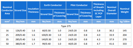
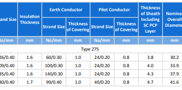
One of the most critical electrical characteristics of the Type 275 cable is its current-carrying capacity, which varies depending on the cross-sectional area of the conductors. The available sizes range from 16mm² to 50mm², with current-carrying capacities ranging from approximately 70 amperes for the smallest size to over 160 amperes for the largest. These ratings assume specific operating conditions, including ambient temperature, cable bundling arrangements, and installation methods.
The cable's electrical performance is also influenced by its insulation system, which uses EPR (Ethylene Propylene Rubber). This insulation material was specifically chosen for mining applications because it maintains its electrical properties across a wide temperature range and resists degradation from ozone, UV light (though this is less relevant underground), and many chemicals. EPR insulation also remains flexible even at low temperatures, which can be important in some underground environments where natural ground temperatures are low.
Cable Structure Breakdown
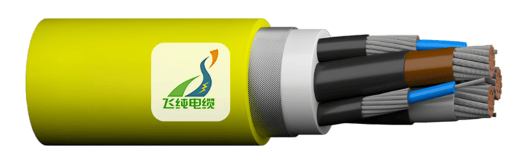
The construction of the Type 275 cable represents a masterpiece of electrical engineering, with each component carefully designed to contribute to the cable's overall performance in the demanding underground mining environment. Understanding the structure of this cable is like understanding the anatomy of a complex organism – each part has a specific function, and they all work together to create a system that can survive in conditions that would destroy simpler designs.
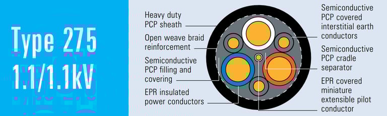
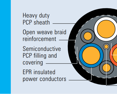
Starting from the inside and working outward, the cable contains three primary power conductors arranged in a triangular configuration. Each of these conductors is made from flexible stranded tinned annealed copper, with the number and size of individual strands varying depending on the overall conductor size. For example, the 16mm² version uses 126 strands of 0.40mm wire, while the 50mm² version uses 380 strands of the same diameter wire. This difference in strand count is crucial – more strands mean greater flexibility, which is essential for cables that will be constantly flexed and bent.
The annealing process mentioned in the specifications refers to a heat treatment that makes the copper softer and more ductile. Annealed copper is more flexible than hard-drawn copper, but it's also slightly less conductive. This trade-off is acceptable in mining applications where flexibility is more important than the small reduction in electrical efficiency.
Surrounding each power conductor is a layer of EPR insulation. The thickness of this insulation varies with the conductor size, ranging from 1.6mm for smaller conductors to 1.7mm for the largest. This insulation must not only provide electrical isolation but also resist the mechanical stresses that occur when the cable is bent and flexed. EPR was chosen specifically because it can handle thousands of flex cycles without cracking or losing its electrical properties.
Between the three power conductors and surrounding the entire assembly is what the specifications call a "cradle separator" made from semiconductive PCP (polychloroprene). This component serves multiple functions that are crucial to the cable's performance. First, it maintains the physical spacing between the three power conductors, ensuring that they don't move around inside the cable as it flexes. Second, the semiconductive properties help to control the electrical field distribution within the cable, reducing the risk of electrical breakdown.
The overall core screen consists of semiconductive PCP filling and covering that surrounds the entire assembly of power conductors and cradle separator. This screen serves as an electrical shield, helping to contain the electrical fields within the cable and providing a degree of protection against electrical interference. In the noisy electrical environment of a mine, where large motors are constantly starting and stopping, this shielding can be crucial for reliable operation.
Embedded within the core assembly are three additional conductors that serve a completely different purpose – the interstitial earth conductors. These are made from flexible stranded tinned copper like the main conductors, but they're smaller and are covered with semiconductive PCP. The term "interstitial" means "occupying spaces between" – these conductors are positioned in the spaces between the main power conductors.
The earth conductors serve two critical functions in mining applications. First, they provide redundant earth connections for safety. If the main earth connection is lost, these conductors ensure that dangerous voltages cannot develop on the equipment frame. Second, and perhaps more importantly in mining applications, these conductors help to share the mechanical load when the cable is under tension. When a shuttle car is pulling its power cable through a mine tunnel, the tension forces are distributed across all the conductors rather than being concentrated on just the main power conductors. This load sharing significantly reduces the risk of conductor breakage.
At the very centre of the cable assembly is the central extensible pilot conductor. This is a single conductor made from flexible stranded tinned copper and covered with EPR insulation. The word "extensible" is key here – this conductor is designed to stretch and compress as the cable is flexed and pulled. The pilot conductor typically carries low-voltage control signals rather than power. It might be used for emergency stop circuits, equipment monitoring, or communication between the mobile equipment and a central control system.
Surrounding the entire core assembly is a textile reinforcement in the form of an open-weave braid. This reinforcement serves as the cable's backbone, providing tensile strength to handle the pulling forces that occur when the cable is dragged behind moving equipment. The open-weave design allows the cable to remain flexible while still providing significant strength. The choice of textile material and weave pattern is critical – it must be strong enough to handle the loads but flexible enough not to restrict the cable's movement.
Finally, the entire assembly is enclosed in a heavy-duty PCP (polychloroprene) sheath. This outer sheath is the cable's first line of defence against the harsh underground environment. It must resist abrasion from being dragged across rough surfaces, chemical attack from acids and alkalis present in mine environments, and physical damage from falling rocks or equipment impacts. The sheath thickness varies with cable size but is typically between 3.8mm and 4.7mm – substantial enough to provide real protection.
For particularly demanding applications, the specifications mention that a heavy-duty CPE/CSP (chlorinated polyethylene/chlorosulfonated polyethylene) sheath can be offered upon request. These alternative sheath materials provide even greater chemical resistance and may be specified for mines where particularly aggressive chemicals are present.
Real-World Use of Mining Slang in Australian Operations
The language of Australian mining is rich with terminology that has evolved over more than a century of underground operations. Understanding how terms like "shuttle," "bogger," and "scoop" are used in real mining contexts provides insight into both the culture of mining and the practical challenges these machines face daily.
In the coal mines of the Hunter Valley, when a shift supervisor radios that "the shuttle's having cable troubles in the back cut," everyone knows exactly what's happening. The "back cut" refers to the furthest working area from the main tunnel, where the shuttle car has been hauling coal from the continuous miner to the conveyor system. Cable troubles in the back cut are particularly problematic because it's the most difficult area to reach for repairs, and every minute of downtime represents tonnes of coal that aren't being extracted.
The term "shuttle" in this context carries with it an understanding of the machine's critical role in the mining operation. Unlike surface mining where large trucks can haul material directly to processing areas, underground operations rely on this shuttle system to move material through the confined spaces of the mine. When miners talk about a shuttle, they're not just referring to a piece of equipment – they're talking about a critical link in the production chain that can make or break the day's output targets.
In the hard rock mines of Western Australia, the terminology shifts slightly but the importance remains the same. A bogger operator might report that "the scoop's dragging cable through the muck in stope five." This simple statement contains layers of meaning that would be immediately understood by other miners but might be incomprehensible to outsiders. The "muck" refers to the broken rock and debris left after blasting, while "stope five" indicates a specific underground chamber where mining is taking place.
The fact that the cable is being "dragged through the muck" immediately tells experienced miners several things: the cable is experiencing higher than normal abrasion, there's a risk of damage from sharp rock fragments, and the cable may be exposed to water and chemical residues from the blasting process. This kind of shorthand communication is essential in mining operations where radio communication may be brief and clarity can be a matter of safety.
In Queensland's underground coal operations, the term "bogger" might be used to describe a different type of machine than in Western Australian gold mines, but the fundamental challenges remain the same. A typical radio conversation might include phrases like "the bogger's cable is getting a workout on the steep grade in section seven." This tells other operators that the cable is under high mechanical stress, possibly from the machine working on an incline where gravity is adding to the tension forces.
The cultural aspect of these terms is also important to understand. In Australian mining, these machines are often referred to with an almost affectionate familiarity. A shuttle isn't just "shuttle car number three" – it might be "old blue" or "the workhorse." This personalisation reflects the dependence that mining operations have on these machines and, by extension, on the cables that power them.
When maintenance crews talk about cable problems, they use specific terminology that reflects the unique challenges of underground operations. A cable might be described as "getting flogged" when it's experiencing heavy wear, or "taking a beating" when it's being subjected to particularly harsh conditions. These terms aren't just colourful language – they represent an understanding of the cable as a component that's actively working under stress rather than simply conducting electricity.
The practical implications of this terminology become clear when you consider how it affects maintenance decisions. When an operator reports that a cable is "getting flogged in the wet areas," the maintenance team immediately knows they need to prioritise inspection of the cable sheath for water ingress and potential chemical damage. This kind of specific, experience-based communication is crucial for maintaining safe and efficient operations.
In the broader context of Australian mining operations, these terms also reflect the practical realities of equipment utilisation. A shuttle that's "running cable" all shift is a productive shuttle, but it's also a shuttle that's putting maximum stress on its power cable. Understanding this relationship between machine utilisation and cable wear is crucial for maintenance planning and operational efficiency.
Installation and Operational Best Practices
The successful deployment of Type 275 1.1/1.1KV cable in underground mining operations requires a deep understanding of both the theoretical principles of cable installation and the practical realities of the mining environment. Proper installation isn't just about following specifications – it's about understanding how the cable will behave under the specific conditions it will encounter and taking steps to maximise its service life while maintaining safety.
The concept of minimum bend radius is perhaps the most critical installation parameter for flexible mining cables. Every cable has a minimum bend radius, typically expressed as a multiple of the cable's overall diameter. For the Type 275 cable, this radius is carefully calculated based on the internal construction and the stress limitations of the various components. Exceeding the minimum bend radius – that is, bending the cable too sharply – can cause internal damage that may not be immediately apparent but will lead to premature failure.
In practical terms, this means that cable reels, pulleys, and any fixed installation points must be sized appropriately. A cable with a 30mm overall diameter might have a minimum bend radius of 300mm, meaning that any curve in the cable installation must have a radius of at least 300mm. In the confined spaces of underground mines, this can present significant challenges, particularly when cables must be routed around existing equipment or through tight spaces.
The installation of cable reeling systems requires particular attention to mechanical design. The reel drum itself must be large enough to accommodate the cable's minimum bend radius, but it also must be designed to handle the tension forces that occur during reeling operations. As a shuttle car moves away from its power source, the cable reel must pay out cable smoothly while maintaining appropriate tension. Too little tension and the cable may become tangled or damaged; too much tension and the cable may be stretched beyond its design limits.
Temperature considerations are often overlooked in cable installations, but they can be critical in underground mining environments. While underground temperatures are generally more stable than surface temperatures, they can still vary significantly depending on depth, geological conditions, and the presence of hot water or steam. The Type 275 cable is designed to operate across a wide temperature range, but extreme conditions may require derating of the current-carrying capacity or special installation precautions.
The grounding system for mining cables deserves special attention because of the safety-critical nature of electrical installations underground. The interstitial earth conductors in the Type 275 cable provide redundant grounding paths, but they must be properly connected at both ends of the cable run. This typically involves specialised connectors that ensure reliable electrical connection while maintaining the flexibility needed for mobile equipment.
Proper connector selection and installation is crucial for reliable operation. Mining cable connectors must be designed to handle not only the electrical loads but also the mechanical stresses of mobile equipment. They must seal against water and dust ingress while remaining easy enough to disconnect for maintenance. The connectors used with Type 275 cable are typically designed with multiple locking mechanisms to prevent accidental disconnection during operation.
Cable support and protection systems must be carefully designed to prevent damage while allowing for the necessary movement. This might include cable tracks or guides that allow the cable to slide smoothly as equipment moves, protection plates that shield the cable from falling rocks, or specialised hangers that support the cable weight without restricting movement.
Regular inspection and maintenance procedures are essential for safe cable operation. Visual inspections should look for signs of sheath damage, such as cuts, abrasions, or chemical attack. Electrical testing should verify insulation integrity and conductor continuity. The central pilot conductor provides an additional monitoring capability – if this conductor fails, it often indicates that the cable is experiencing excessive mechanical stress that could lead to power conductor failure.
Documentation of cable installations is particularly important in mining operations where multiple shifts of workers may be responsible for the same equipment. Installation records should include cable routing information, connector specifications, testing results, and any special installation considerations. This documentation becomes crucial when troubleshooting problems or planning maintenance activities.
Troubleshooting and Common Issues: Comprehensive FAQ
The harsh environment of underground mining creates unique challenges for electrical equipment, and the Type 275 1.1/1.1KV cable, despite its robust construction, can experience problems that require systematic troubleshooting approaches. Understanding these common issues and their solutions is essential for maintaining safe and efficient mining operations.
What happens if the cable sheath is damaged, and how quickly must it be addressed?
Sheath damage represents one of the most serious threats to cable integrity in mining operations, and the response must be swift and comprehensive. When the outer sheath is compromised, the cable loses its primary defence against the harsh underground environment. Water, chemicals, and abrasive particles can penetrate the damaged area and begin attacking the internal components of the cable.
The immediate risk from sheath damage is water ingress, which can cause several cascading problems. First, water can degrade the insulation system, leading to reduced dielectric strength and eventual electrical breakdown. Second, water can cause corrosion of the copper conductors, particularly at strand interfaces where capillary action can draw moisture deep into the conductor. Third, water can freeze in cold environments, causing physical damage to the cable structure.
Chemical ingress through damaged sheath areas can be even more destructive than water. Many mining operations use chemicals for dust suppression, ore processing, or equipment cleaning, and these chemicals can rapidly degrade cable insulation and conductors. Some chemicals can cause the EPR insulation to swell, crack, or lose its electrical properties entirely.
The replacement decision should be made immediately upon discovery of significant sheath damage. While minor surface scratches might be repairable with appropriate sealing compounds, any damage that penetrates completely through the sheath requires cable replacement. Attempting to operate with damaged sheath integrity risks not only equipment damage but also serious safety hazards including electrical shock, fire, and explosion risks in potentially explosive atmospheres.
How can wire breaks during tension be minimised, and what role do the earth cores play?
Understanding tension-related failures requires appreciating the complex mechanical forces that act on mining cables during normal operation. When a shuttle car or bogger moves through the mine while connected to a power cable, the cable experiences varying tension forces depending on the equipment's position, the cable routing, and any obstacles the cable encounters.
The interstitial earth conductors play a crucial mechanical role beyond their electrical safety function. These conductors are strategically positioned within the cable construction to share mechanical loads with the main power conductors. When the cable is under tension, the forces are distributed across all the conductors rather than being concentrated solely on the three main power conductors. This load sharing significantly reduces the stress on individual conductors and helps prevent the fatigue failures that can occur with repeated loading cycles.
Proper cable routing is perhaps the most important factor in preventing tension-related failures. The cable path should be planned to minimise sharp bends, avoid obstacles that could cause snagging, and ensure that the cable can move freely as the equipment operates. Cable guides and supports should be positioned to maintain the cable's minimum bend radius while allowing for the full range of equipment movement.
Tension monitoring systems can provide early warning of excessive cable stress. These systems typically monitor the force required to pay out or reel in cable and can alert operators when tensions exceed safe limits. Some advanced systems can automatically adjust equipment operation to reduce cable stress when excessive tensions are detected.
The central extensible pilot conductor also contributes to tension management. This conductor is designed to stretch and compress with cable movement, providing a degree of strain relief for the entire cable assembly. Monitoring the continuity of this conductor can provide early indication of excessive mechanical stress before main power conductors are affected.
Is the Type 275 cable suitable for wet environments, and what specific protections does it offer?
Underground mining environments are frequently wet, with water infiltration occurring through natural seepage, hydraulic systems, or dust suppression systems. The Type 275 cable is specifically designed to handle these conditions, but understanding its limitations and proper application is crucial for reliable operation.
The heavy-duty PCP sheath provides excellent water resistance under normal operating conditions. PCP (polychloroprene) is inherently water-resistant and maintains its sealing properties across a wide temperature range. The sheath thickness of 3.8mm to 4.7mm provides substantial protection against water ingress, even when the cable is subjected to significant hydrostatic pressure.
However, water resistance depends on sheath integrity. Any damage to the sheath can compromise the cable's water resistance, which is why regular inspection and immediate repair of sheath damage is so critical. The cable's resistance to water also depends on proper connector sealing. Even the best cable can fail if water enters through poorly sealed connections.
For extremely wet conditions or applications where the cable may be submerged, additional precautions may be necessary. This might include more frequent inspection schedules, redundant sealing systems, or consideration of the optional heavy-duty CPE/CSP sheath materials that offer enhanced chemical and water resistance.
The cable's internal construction also provides some protection against water ingress. The semiconductive PCP components help prevent water migration along the cable length if minor ingress does occur. However, this should be considered a backup protection rather than a primary defence against water.
Can the Type 275 cable be used on vertical reeling systems, and what special considerations apply?
Vertical reeling applications present unique challenges that require careful evaluation of the cable's mechanical properties and the reeling system design. While the Type 275 cable is designed for flexible reeling applications, vertical installations create additional stresses that may not be present in horizontal systems.
The primary concern with vertical reeling is the additional tension created by the cable's own weight. In a horizontal system, the cable tension is primarily determined by the drag forces as the cable moves across surfaces. In a vertical system, the weight of the suspended cable adds significantly to this tension, particularly for long cable runs.
The cable's tensile strength specifications must be carefully compared to the expected loads in vertical applications. This includes not only the static weight of the suspended cable but also the dynamic loads that occur during reeling operations. The textile reinforcement in the Type 275 cable provides significant tensile strength, but this must be verified against the specific application requirements.
Vertical reeling systems also require special attention to cable support and guidance. The cable must be prevented from spinning or twisting as it pays out, which could cause internal damage. Specialized cable guides and support systems may be required to maintain proper cable geometry during vertical operation.
The reeling mechanism itself must be designed to handle the additional loads of vertical operation. This typically requires larger, more robust reeling drums and higher-capacity drive systems. Safety systems must also be enhanced to prevent uncontrolled cable release in the event of drive system failure.
What are the signs of chemical attack on the cable, and how should it be addressed?
Chemical attack on mining cables can be insidious, often beginning with subtle changes in sheath appearance or flexibility before progressing to serious structural damage. Understanding the signs of chemical attack and responding appropriately is crucial for maintaining safe operations.
Early signs of chemical attack often appear as changes in the cable sheath color, texture, or flexibility. The sheath may become discolored, developing unusual staining or color changes that weren't present during installation. The surface texture might change, becoming either unusually smooth and glossy or rough and pitted. The sheath material might become either harder and more brittle or softer and more pliable than normal.
More advanced chemical attack may cause the sheath to crack, peel, or delaminate. In severe cases, the sheath might actually dissolve or be chemically converted to a different material entirely. These advanced stages of chemical attack represent serious safety hazards and require immediate cable replacement.
The specific chemicals present in mining environments vary greatly depending on the type of mining operation, ore processing methods, and safety procedures. Coal mines might have issues with acidic water from sulfur compounds in the coal. Metal mines might have problems with acids used in ore processing or alkalis used in flotation processes. Each type of chemical attack requires different protective measures.
When chemical attack is suspected, the first step is to identify the attacking chemical if possible. This information is crucial for selecting appropriate replacement cables and implementing protective measures. Samples of the damaged cable sheath can sometimes be analyzed to identify the attacking chemical and assess the extent of damage.
Prevention of chemical attack requires understanding the chemical environment and selecting appropriate cable materials. The standard PCP sheath provides good resistance to many chemicals, but the optional CPE/CSP sheath materials may be necessary for particularly aggressive chemical environments.
How should cable performance be monitored during operation?
Effective cable monitoring requires a combination of visual inspection, electrical testing, and operational monitoring that can detect problems before they lead to failures. The central pilot conductor in the Type 275 cable provides an additional monitoring capability that can be particularly valuable in mining applications.
Visual inspection should be conducted regularly and should focus on several key areas. The cable sheath should be examined for cuts, abrasions, chemical staining, or unusual wear patterns. Particular attention should be paid to areas where the cable bends sharply or comes into contact with equipment or structures. The connectors should be inspected for signs of overheating, corrosion, or mechanical damage.
Electrical testing should include insulation resistance measurements between conductors and between conductors and earth. These measurements can detect insulation degradation before it leads to complete failure. The tests should be conducted with appropriate high-voltage test equipment and should follow established safety procedures for testing energized equipment.
The central pilot conductor provides a unique monitoring opportunity. This conductor can be used to monitor cable continuity and can provide early warning of mechanical damage. Some operations use the pilot conductor for continuous monitoring systems that can alert operators immediately if the conductor is damaged.
Operational monitoring should track cable performance parameters such as reel tension, cable temperature, and any unusual operational characteristics. Modern mining equipment often includes data logging capabilities that can track these parameters over time and identify trends that might indicate developing problems.
Temperature monitoring is particularly important for heavily loaded cables. Excessive temperatures can indicate overloading, Poor ventilation, or developing electrical problems. Some operations use infrared temperature monitoring to regularly check cable and connector temperatures during operation.
Standards Compliance and Regulatory Framework
The Type 275 1.1/1.1KV mining cable operates within a comprehensive framework of Australian and New Zealand standards that ensure safety, performance, and interoperability in mining applications. Understanding these standards and their requirements is crucial for proper cable selection, installation, and operation.
AS/NZS 1802:2003 represents the primary standard governing reeling and trailing cables in mining applications. This standard establishes the fundamental requirements for cables intended for mobile equipment in mining operations. It addresses not only the electrical characteristics of the cables but also their mechanical properties, environmental resistance, and safety features. The standard recognises that mining cables operate in uniquely challenging environments and establishes requirements that go well beyond those for general-purpose electrical cables.
The standard's requirements for mechanical properties are particularly stringent, recognising that mining cables must withstand repeated flexing, tension, compression, and abrasion that would quickly destroy cables designed for stationary applications. The standard establishes minimum requirements for tensile strength, flex life, and abrasion resistance that ensure cables can survive the harsh realities of underground mining operations.
AS/NZS 1125 governs the construction and properties of electrical conductors. This standard ensures that the copper conductors used in the Type 275 cable meet strict requirements for electrical conductivity, mechanical strength, and durability. The standard's requirements for strand construction, tinning, and annealing ensure that the conductors can handle both the electrical loads and mechanical stresses encountered in mining applications.
The conductor requirements also address the important issue of strand breakage under repeated flexing. The standard establishes testing procedures that simulate the flexing conditions that mining cables experience and sets minimum performance requirements that ensure adequate service life. These requirements are particularly important for the interstitial earth conductors, which must maintain their integrity to provide the safety and mechanical benefits they're designed to deliver.
AS/NZS 3808 addresses the insulation systems used in mining cables. This standard recognises that cable insulation in mining applications must withstand not only electrical stress but also thermal cycling, mechanical deformation, and chemical exposure. The EPR insulation used in the Type 275 cable must meet strict requirements for dielectric strength, thermal stability, and resistance to various environmental factors.
The insulation standard also addresses the important issue of partial discharge, which can occur in high-voltage cable systems and can lead to gradual degradation of the insulation system. The standard establishes requirements for insulation design and testing that minimise the risk of partial discharge and ensure long-term reliability of the cable system.
AS/NZS 5000.1 provides the overarching framework for low-voltage cables, establishing general requirements for design, construction, and testing. While the specific requirements for mining cables are addressed in the more specialised standards, AS/NZS 5000.1 provides important guidance on fundamental electrical and safety principles that apply to all cable installations.
Compliance with these standards involves extensive testing during cable manufacture, including electrical tests, mechanical tests, and environmental exposure tests. The testing procedures are designed to verify that the cables will perform reliably under the specific conditions they will encounter in mining operations.
The standards also establish requirements for cable marking and identification, ensuring that cables can be properly identified and their specifications verified during installation and maintenance. This traceability is particularly important in mining operations where cable failures can have serious safety and economic consequences.
Regular updates to these standards reflect evolving technology and operational experience. Cable manufacturers and mining operators must stay current with standard revisions to ensure continued compliance and optimal performance. The standards development process typically involves extensive consultation with industry stakeholders, including mining companies, cable manufacturers, and safety regulators.
Conclusion
The Type 275 1.1/1.1KV mining cable represents a sophisticated engineering solution to one of the most challenging electrical applications in industrial operations. In the unforgiving environment of underground mining, where equipment failure can mean the difference between a productive day and a dangerous situation, this cable serves as a critical lifeline that must perform reliably under conditions that would destroy conventional electrical cables within hours.
The cable's multi-layered construction, from its flexible stranded copper conductors to its heavy-duty protective sheath, reflects decades of engineering experience and operational feedback from mining operations across Australia and around the world. Each component of the cable's design serves multiple purposes, contributing not only to electrical performance but also to mechanical durability and operational safety.
The integration of interstitial earth conductors and the central extensible pilot demonstrates how modern cable design addresses both safety and operational monitoring requirements. These features provide redundant safety systems and early warning capabilities that are essential in environments where equipment failure can have serious consequences for both personnel safety and operational continuity.
For mining operators, the Type 275 cable offers a proven solution for powering shuttle cars, boggers, and scoops in the demanding underground environment. Its compliance with Australian and New Zealand standards ensures compatibility with existing equipment and installation practices, while its robust construction provides the reliability needed for continuous operation in harsh conditions.
The cable's flexibility characteristics make it particularly well-suited for the dynamic requirements of mobile mining equipment. Whether being reeled and unreeled hundreds of times per shift on a shuttle car or dragged through rough terrain behind a bogger, the Type 275 cable maintains its electrical and mechanical integrity through thousands of operating cycles.
Understanding the proper application, installation, and maintenance of this cable is crucial for maximising its service life and ensuring safe operation. The comprehensive approach to cable management, from initial selection through ongoing monitoring and maintenance, represents best practices that have evolved through years of operational experience in some of the world's most challenging industrial environments.
The economic impact of proper cable selection and management cannot be overstated in mining operations where downtime costs can easily reach thousands of dollars per hour. The Type 275 cable's proven reliability and durability make it an investment in operational continuity that pays dividends through reduced maintenance costs, fewer unplanned shutdowns, and improved safety performance.
As mining operations continue to evolve, with deeper mines, more demanding extraction methods, and increasingly sophisticated equipment, the role of reliable electrical infrastructure becomes even more critical. The Type 275 1.1/1.1KV cable, with its combination of electrical performance, mechanical durability, and operational flexibility, will continue to serve as a backbone component in the electrical systems that power Australia's vital mining industry.
The cable's design philosophy of prioritising flexibility, durability, and safety over cost optimisation reflects the mining industry's understanding that in underground operations, reliability is not just an economic consideration but a fundamental safety requirement. In the depths of a mine, where rescue and repair operations are complex and time-consuming, having electrical systems that can be trusted to perform reliably is not just desirable – it's essential.
For maintenance teams, engineers, and operators working in underground mining operations, the Type 275 cable represents a proven tool in the ongoing challenge of maintaining safe, efficient, and profitable mining operations. Its robust construction, comprehensive compliance with applicable standards, and proven track record in demanding applications make it an ideal choice for powering the critical mobile equipment that keeps Australia's mines productive and safe.
Key Takeaways:
Type 275 1.1/1.1KV cable is specifically engineered for the unique challenges of underground mining applications
Flexible construction with interstitial earth conductors provides both electrical performance and mechanical durability
Proper installation, monitoring, and maintenance are essential for maximising cable service life
Compliance with AS/NZS standards ensures safety and compatibility with existing mining infrastructure
The cable's proven reliability makes it an essential component in modern mining operations where downtime is costly and safety is paramount

