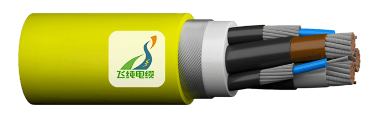
Type 2S 1.1/1.1 kV Collectively Screened Mining Cable: The Underground Workhorse for Shuttle Cars and Underground Loaders
Comprehensive guide to Type 2S 1.1/1.1 kV collectively screened mining cables for shuttle cars, boggers, and scoops. Learn about construction, installation, electrical parameters, and troubleshooting in Australian mining operations.
6/17/202523 min read
Type 2S 1.1/1.1 kV Collectively Screened Mining Cable: The Underground Workhorse for Shuttle Cars and Underground Loaders
Introduction
Deep beneath the Australian earth, where sunlight never penetrates and the air is thick with dust and moisture, a complex ballet of machinery keeps our mining industry running. At the heart of this underground symphony are the workhorses we know by their colloquial names: shuttles, boggers, and scoops. These aren't just pieces of equipment—they're the lifelines that connect raw earth to the surface world, hauling precious ore through narrow tunnels and cramped spaces where larger machinery simply cannot venture.
What is a Shuttle Car, Bogger, or Underground Loader?
Picture this: you're standing in a mine tunnel barely wide enough for two people to pass comfortably, yet somehow a machine needs to navigate this space while carrying tonnes of ore. This is where shuttle cars, underground loaders (commonly called "scoops" by miners), and boggers earn their keep. These compact, powerful vehicles are the unsung heroes of underground mining operations across Australia, from the coal seams of Queensland's Bowen Basin to the hard rock mines of Western Australia's Pilbara region.
A shuttle car, or "shuttle" as it's known on site, operates much like an underground taxi service for ore. These low-profile, battery-powered or trailing cable-fed vehicles collect material from the face where it's been blasted or cut, then transport it to a central loading point or conveyor system. The shuttle's design prioritises manoeuvrability over size—it needs to squeeze through spaces that would challenge even the most skilled driver on the surface.
Boggers and scoops serve similar functions but with different approaches. A bogger typically refers to a load-haul-dump (LHD) vehicle that can both collect material and transport it, while a scoop generally describes the loading mechanism itself, though miners often use these terms interchangeably depending on their regional dialect and the specific type of equipment they're operating.
These machines face challenges that surface equipment never encounters. They must operate in environments where ceiling heights might be less than two metres, where water constantly seeps through rock joints, and where the air itself can become electrically charged with dust particles. The reliability of these vehicles isn't just about productivity—in many cases, they represent the only means of evacuation for workers in emergency situations.
Why Power and Signal Integrity Matter Underground
Understanding the electrical challenges faced underground requires thinking beyond simple power delivery. In a typical surface industrial application, electrical interference might cause minor inconvenience or slightly reduced efficiency. Underground, electrical problems can mean the difference between a productive shift and a dangerous situation.
The underground environment presents a perfect storm of electrical challenges. Water ingress is constant—not just from obvious sources like underground streams, but from the natural moisture that condenses on cold surfaces when warm air moves through the mine. This moisture carries dissolved minerals that make it highly conductive, creating paths for electrical current that shouldn't exist.
Dust presents another layer of complexity. Coal dust isn't just dirty—it can become electrically conductive under certain conditions and poses serious explosion risks if ignited by electrical arcs. Hard rock dust, while less explosive, is incredibly abrasive and can work its way into electrical connections, creating resistance and heat that leads to failures.
Mechanical stress on cables is relentless. Unlike surface installations where cables might be routed through protective conduits and remain stationary, underground cables must flex and move constantly. Shuttle cars don't travel on smooth roads—they navigate over broken rock, around tight corners, and through spaces where every millimetre of clearance matters. The cables that power and control these machines must endure thousands of flex cycles while maintaining perfect electrical integrity.
This is where the sophisticated engineering of Type 2S collectively screened cables becomes crucial. These aren't just heavy-duty versions of ordinary cables—they're purpose-built solutions for an environment that would destroy conventional electrical systems within days.


Cable Electrical Fundamentals and Australian Standards
Understanding the 1.1 kV Rating
When we talk about a 1.1 kV cable rating, we're describing its ability to safely handle electrical potential differences of 1,100 volts between conductors or between any conductor and earth. This might seem like an arbitrary number, but it reflects decades of engineering experience in underground applications.
In the Australian electrical classification system, 1.1 kV falls into the medium voltage category, sitting above low voltage (typically 230V to 1000V) but well below high voltage systems. This voltage level provides several critical advantages in underground mining applications.
The higher voltage allows for more efficient power transmission over the longer distances common in mining operations. When shuttle cars need to operate hundreds of metres from their power source, voltage drop becomes a significant concern. By starting with 1.1 kV instead of standard 415V three-phase power, engineers can maintain adequate voltage at the load even after accounting for cable resistance and connection losses.
The 1.1 kV rating also provides important safety margins. Underground environments are unpredictable, and electrical systems may experience temporary overvoltages due to switching operations, lightning-induced surges transmitted through the mine's electrical infrastructure, or faults in other parts of the system. The robust insulation system designed for 1.1 kV operation provides confidence that these transient events won't cause immediate failures.
Collectively Screened Design Philosophy
The term "collectively screened" describes one of the most important features of these cables, though it's often the least understood by those who haven't worked extensively with underground electrical systems. Think of the collective screen as an electrical shield that surrounds all the power conductors together, rather than individual shields around each conductor.
This overall copper braid screen serves multiple critical functions simultaneously. First, it acts as an earth conductor, providing a low-resistance path for fault currents back to the system's earthing point. In underground applications, this earth path is crucial for both safety and equipment protection—if a conductor comes into contact with the machine's frame, the screen ensures that protective devices operate quickly to clear the fault.
The screen also provides electromagnetic interference (EMI) suppression. Underground mines are electrically noisy environments, with variable frequency drives, switching equipment, and radio communications all potentially interfering with sensitive control systems. The copper braid acts as a Faraday cage, containing electromagnetic emissions from the cable itself while also protecting the circuits inside from external interference.
Perhaps most importantly for mining applications, the collective screen provides mechanical protection. The interwoven copper and polyester construction creates a tough, flexible barrier that resists abrasion while maintaining electrical continuity even as the cable flexes through its normal duty cycle.
Australian Standards Compliance
The Type 2S cable's compliance with AS/NZS 1972:2006, AS/NZS 1125, and AS/NZS 3808 isn't just regulatory box-ticking—these standards represent the accumulated wisdom of decades of Australian mining experience.
AS/NZS 1972:2006 covers insulation coordination for high-voltage installations, ensuring that the cable's insulation system can withstand not just normal operating voltages but also the transient overvoltages that occur during fault conditions or switching operations. This standard recognises that underground electrical systems experience more severe electrical stresses than surface installations.
AS/NZS 1125 addresses the specific requirements for mining cables, including flame resistance, oil resistance, and mechanical durability. This standard emerged from hard-learned lessons about what happens when cables fail underground—the consequences extend far beyond simple power outages.
AS/NZS 3808 focuses on the particular challenges of trailing cable applications, where cables must maintain integrity while being dragged, flexed, and twisted through their service life. This standard recognises that mining cables aren't just installed once and forgotten—they're active participants in the mining operation, moving and flexing thousands of times per shift.
Cable Construction and Technical Specifications
Conductor Design and Materials
The heart of any electrical cable lies in its conductors, and the Type 2S cable employs stranded tinned annealed copper conductors that represent a careful balance of electrical, mechanical, and economic considerations. Let's unpack why each of these design elements matters in underground applications.
The choice of copper over aluminium reflects the harsh realities of underground service. While aluminium conductors are lighter and less expensive, copper's superior corrosion resistance and mechanical properties make it the only practical choice for trailing cable applications. Underground moisture inevitably finds its way into electrical systems, and copper's natural corrosion resistance provides a crucial margin of safety.
The stranding pattern—30 individual wires of 0.25mm diameter for 1.5mm² conductors—isn't arbitrary. This fine stranding provides the flexibility essential for cables that must flex continuously without work-hardening and breaking. Each individual strand is small enough to bend easily, while the overall conductor cross-section provides adequate current-carrying capacity.
Tinning of the copper strands adds another layer of protection. The thin tin coating prevents oxidation of the copper surface, which could increase resistance and create heat buildup over time. In underground environments where humidity is often near 100%, this protection becomes critical for long-term reliability.
The annealing process—controlled heating and cooling of the copper—ensures that the metal remains soft and flexible even after the stranding process. Hard-drawn copper might provide slightly better conductivity, but it would crack under the constant flexing required in shuttle car service.
Insulation System Engineering
The choice of EPR (ethylene propylene rubber) insulation represents decades of evolution in cable design for harsh environments. EPR isn't just another type of rubber—it's a carefully engineered polymer system designed to maintain its electrical and mechanical properties across the wide temperature and environmental ranges encountered underground.
EPR's temperature rating allows operation from -40°C to +90°C, covering the range from winter surface conditions (where vehicles might be parked) to the elevated temperatures that can occur in deep mines or near heat sources. This wide temperature range is crucial because cable insulation that becomes brittle in cold conditions or soft in hot conditions won't survive the mechanical stresses of underground service.
The polymer's resistance to ozone, oxygen, and ultraviolet light means it won't degrade even if exposed to surface conditions during maintenance or storage. Many other rubber compounds break down when exposed to these environmental factors, leading to insulation failures that might not become apparent until the cable is returned to service.
Perhaps most importantly, EPR maintains its flexibility throughout its service life. Other insulation materials might start flexible but gradually harden due to chemical changes in the polymer structure. EPR's molecular composition resists these changes, ensuring that cables remain flexible even after years of service.
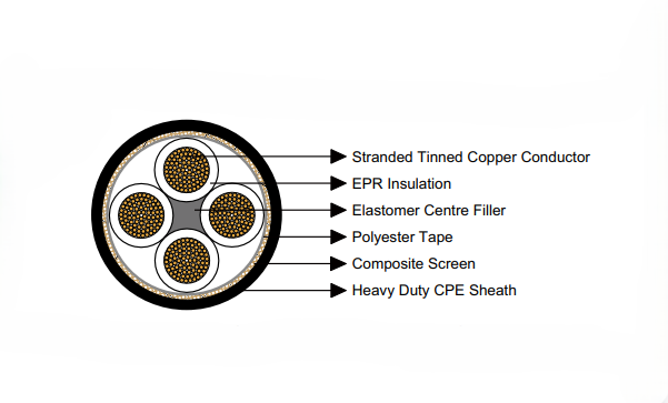
Structural Elements and Their Functions
The elastomer centre filler might seem like a minor component, but it plays several critical roles in cable performance. By maintaining the cable's round cross-section, the filler ensures even stress distribution during bending and prevents the development of stress concentrations that could lead to insulation failures.
The polyester tape bedding provides a smooth, uniform surface for the application of the collective screen. Without this bedding layer, the screen could dig into the underlying insulation during cable flexing, eventually causing failures. The polyester material is chosen for its resistance to moisture and chemicals that might be present in underground environments.
The composite screen construction—tinned copper braid interwoven with polyester yarn—represents sophisticated engineering. The copper provides electrical conductivity for earthing and EMI shielding, while the polyester yarn adds mechanical strength and helps maintain screen integrity during flexing. The interwoven construction ensures that even if individual copper strands break due to repeated flexing, the overall screen continuity is maintained.
Outer Sheath Engineering
The heavy-duty CPE (chlorinated polyethylene) sheath is the cable's first line of defence against the underground environment. CPE's chemical structure provides exceptional resistance to oils, fuels, and the various chemicals used in mining operations. Unlike PVC, which can become brittle at low temperatures or soft at high temperatures, CPE maintains its toughness across the full range of mining conditions.
The sheath's cut and abrasion resistance is crucial for cables that might be dragged across sharp rock edges or pinched between moving machinery parts. The material's tear resistance means that small nicks or cuts won't propagate into major failures, providing time for scheduled replacement before catastrophic failure occurs.
Dimensional Analysis and Practical Implications
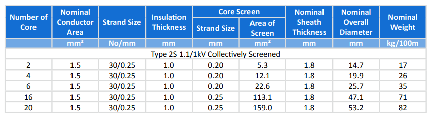
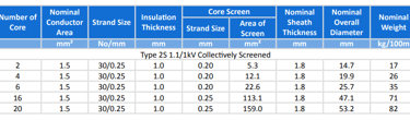
Looking at the dimensional table, we can see how cable size affects practical installation and operation. A 2-core 1.5mm² cable with its 14.7mm overall diameter and 17 kg/100m weight represents the minimum practical size for most shuttle car applications. The relatively small size and light weight make it suitable for control circuits or auxiliary power, where flexibility and ease of handling are paramount.
At the other end of the spectrum, a 20-core cable with its 53.2mm diameter and 82 kg/100m weight represents a significant physical presence. This size cable requires careful consideration of bend radii, support systems, and handling equipment. The weight alone means that installation must be planned carefully—manual handling becomes impractical for anything but short sections.
The screen area progression from 5.3mm² in the smallest cable to 159.0mm² in the largest reflects the increasing earth fault current capacity required for higher-powered installations. This isn't just about meeting electrical codes—it's about ensuring that earth faults clear quickly and safely, minimising both equipment damage and safety risks.
Installation Guidelines and Underground Mining Culture
Installation Specifications and Best Practices
Installing Type 2S collectively screened cables underground isn't simply a matter of running them from point A to point B. The installation process must account for the unique challenges of an environment where everything is working against you—gravity, water, abrasion, and the constant movement of machinery.
The minimum bend radius specifications aren't arbitrary numbers pulled from engineering handbooks. They represent the physical limits beyond which the cable's internal structure begins to suffer permanent damage. For these cables, the minimum bend radius is typically 6 to 8 times the overall cable diameter during installation, and 4 to 6 times the diameter for fixed installations. This means our largest 20-core cable requires bend radii of over 300mm during installation—a significant constraint in tight underground spaces.
Pulling tension limits are equally critical. While the cable's construction is robust, excessive pulling forces during installation can stretch the conductors, compress the insulation, or damage the screen continuity. Maximum pulling tensions are typically limited to 50-70 Newtons per square millimetre of conductor cross-sectional area, which means careful calculation and monitoring during cable installation.
The underground environment demands special attention to environmental factors that surface installations rarely encounter. Moisture ingress isn't a question of if, but when and how much. Cable entry points into equipment must be sealed with appropriate glands that maintain their integrity despite constant movement and vibration. Temperature variations can be extreme—from near-freezing conditions in winter to elevated temperatures near machinery or in deeper mine sections.
Mining Slang and Practical Terminology
Understanding the language of underground mining is essential for anyone working with this equipment. When a miner talks about "drag-roping," they're describing the process of pulling cables through tight spaces—often by hand, sometimes with the help of winches or the vehicles themselves. This term captures the physical reality of cable installation underground, where sophisticated cable-pulling equipment often can't fit.
The "chute" refers to the opening through which ore is loaded into shuttle cars. Cable routing around chutes requires special consideration because these areas see constant traffic from both machinery and falling material. Cables in these areas often require additional protection in the form of steel troughs or flexible convoluted hose.
A "tow-point" is where the cable connects to the moving machinery. This connection point experiences the highest mechanical stress in the entire installation, as it must transfer all the cable's weight and drag forces to the vehicle. Proper strain relief at tow-points isn't just good engineering practice—it's essential for preventing premature cable failures.
The term "umbilical" is used to describe the complete cable assembly that powers and controls a piece of mobile equipment. Like a biological umbilical cord, this cable is the lifeline that keeps the equipment functioning. When miners say they're "checking the umbilical," they're performing the routine inspections that prevent unexpected failures.
Underground Installation Techniques
Best practices for underground cable installation have evolved through decades of hard-learned lessons. Loops for movement aren't just recommendations—they're essential design elements that accommodate the natural movement of machinery without overstressing the cable. These loops must be sized correctly: too small and they restrict movement, too large and they become snagging hazards.
Strain relief at pivot points requires mechanical engineering as much as electrical engineering. The strain relief must transfer mechanical loads to the equipment structure without creating stress concentrations in the cable. This often involves custom-manufactured clamps and supports designed for the specific application.
Protective convoluted hose serves multiple functions beyond simple abrasion protection. It provides a smooth outer surface that resists snagging, distributes bending forces over a longer cable length, and provides additional protection against impact damage. The choice of protective hose material must consider chemical compatibility with underground environments—standard PVC hose might not survive exposure to some mining chemicals.
Electrical bonding of the cable screen to equipment frames isn't just about meeting electrical codes. Proper bonding ensures that fault currents have a low-impedance path back to the system earthing point, enabling protective devices to operate correctly. Poor bonding can result in dangerous touch voltages on equipment frames during fault conditions.
Field Application: Cable Performance in Real Mining Operations
Mine Profile and Operating Environment
Consider a typical Australian underground coal mine in the Hunter Valley of New South Wales. The mine operates multiple shuttle cars in a room-and-pillar configuration, with each shuttle serving a development heading approximately 400 metres from the main transportation drift. The seam height varies from 2.8 to 3.2 metres, providing just enough clearance for shuttle car operation.
Environmental conditions in this mine are typical of Australian underground coal operations. Ambient temperature ranges from 15°C near the portal to 25°C at the working faces due to geothermal heating and equipment operation. Relative humidity consistently approaches 100% due to groundwater seepage and limited ventilation air flow to development headings.
The mine operates three shuttle cars per shift, with each car making approximately 15 round trips per shift. This means each cable experiences roughly 30 significant flex cycles per day, or over 10,000 flex cycles per year. When multiplied by the partial flexing that occurs during loading and positioning operations, the total flex count easily exceeds 50,000 cycles annually.
Rock conditions in the mine present ongoing challenges for cable installations. The immediate roof consists of relatively soft shale that occasionally spalls, creating sharp edges and uneven surfaces. Floor conditions vary from stable coal to soft clay that becomes slippery when wet, creating traction challenges for shuttle cars that result in additional cable stress as vehicles work to maintain progress.
Application Scenario and Daily Operations
A typical shuttle car operation begins each shift with a thorough inspection of all electrical systems, including visual examination of the trailing cable for obvious damage. The operator checks the cable's overall condition, looking for cuts, abrasions, or deformation that might indicate internal damage.
During operation, the shuttle car travels from the loading point to the discharge point, with the cable following behind in a carefully managed configuration. The cable must accommodate not just the linear travel distance, but also the turning movements required to position the car for loading and discharge. At the face, the shuttle positions itself under the continuous miner's discharge conveyor, requiring precise maneuvering in confined spaces.
The cable routing follows a predetermined path that avoids obstacles while minimising sharp bends and potential snagging points. Temporary cable supports—often nothing more than wooden blocks or steel brackets—help maintain proper cable geometry during operation. These supports must be repositioned regularly as mining operations advance and retreat patterns change.
Cable length in this application typically exceeds 500 metres, requiring careful attention to voltage drop calculations and protection coordination. The cable's 1.5mm² conductors provide adequate current carrying capacity for the shuttle car's drive motors, while larger conductors handle high-current loads like the loading conveyor motor.
Performance Monitoring and Maintenance
Regular performance monitoring of underground cables goes beyond simple visual inspection. Electrical testing includes insulation resistance measurements using high-voltage megohmmeters, continuity testing of all conductors and the collective screen, and periodic high-potential testing to verify insulation integrity.
Thermal monitoring has become increasingly important as equipment power levels have increased. Infrared thermography can identify hot spots that indicate developing problems—perhaps increased resistance due to damaged conductors or poor connections. These hot spots often appear long before they become serious enough to cause immediate failures.
Mechanical inspection focuses on the cable's physical condition, particularly at high-stress points like the tow-point connection and areas where the cable passes over or around obstacles. Experienced maintenance personnel can often predict cable failures by identifying early signs of mechanical degradation—subtle changes in cable flexibility, surface wear patterns, or deformation that indicates internal damage.
The maintenance schedule for these cables typically involves daily visual inspections by equipment operators, weekly detailed inspections by maintenance personnel, monthly electrical testing, and annual comprehensive testing including high-potential tests and detailed mechanical examination.
Product Structure Breakdown and Engineering Analysis
Layer-by-Layer Construction Analysis
Understanding the Type 2S cable's construction requires examining each layer's specific contribution to overall performance. Starting from the inside and working outward, each element serves multiple functions that contribute to the cable's ability to survive underground mining service.
The stranded tinned copper conductors form the electrical heart of the system, but their mechanical properties are equally important. The fine stranding pattern allows the conductors to flex repeatedly without work-hardening, while the tin coating prevents corrosion that could increase resistance over time. The conductor's temperature coefficient must be considered in applications where ambient temperature varies significantly—copper's resistance increases with temperature, affecting both electrical performance and thermal management.
The EPR insulation layer provides electrical isolation between conductors and between conductors and the collective screen. The insulation thickness—1.0mm for 1.5mm² conductors—provides substantial electrical strength while maintaining flexibility. The dielectric properties of EPR remain stable across the wide temperature range encountered in mining operations, ensuring consistent electrical performance regardless of environmental conditions.
The elastomer centre filler maintains the cable's geometric integrity during flexing while providing additional mechanical protection for the inner conductors. This filler material must be compatible with the EPR insulation to prevent chemical interactions that could cause premature aging. The filler's durometer—its hardness—is carefully chosen to provide support without creating rigid zones that could cause stress concentrations during bending.
The polyester tape bedding provides a smooth, uniform surface for the collective screen while preventing the screen from embedding into the underlying structure during cable flexing. The tape's thickness and overlap pattern are designed to provide complete coverage while minimising overall cable diameter.
Collective Screen Engineering
The composite screen construction represents one of the most sophisticated aspects of the cable design. The tinned copper braid provides electrical conductivity for both earthing and electromagnetic shielding functions, while the interwoven polyester yarn adds mechanical strength and maintains screen integrity during repeated flexing.
The screen's electrical characteristics are carefully engineered to meet multiple requirements simultaneously. As an earth conductor, it must carry fault currents safely without excessive voltage drop or thermal damage. The screen area—ranging from 5.3mm² in the smallest cable to 159.0mm² in the largest—is sized to handle expected fault current levels while providing appropriate safety margins.
As an electromagnetic shield, the screen must provide effective attenuation of both electric and magnetic field components across the frequency ranges of concern in mining operations. Variable frequency drives, radio communications, and switching equipment all generate electromagnetic emissions that could interfere with sensitive control systems. The screen's coverage—typically exceeding 85% of the cable's circumference—provides effective shielding while maintaining the flexibility essential for trailing cable applications.
The mechanical properties of the composite screen are equally important. The interwoven construction ensures that individual wire breaks don't compromise overall screen integrity. As the cable flexes, some individual copper strands will inevitably fatigue and break, but the polyester yarn maintains mechanical continuity while remaining copper strands maintain electrical continuity.
Outer Sheath Protection System
The heavy-duty CPE sheath serves as the cable's primary defence against the underground environment. The material selection reflects the harsh realities of mining service, where cables are exposed to water, oils, fuels, chemicals, abrasion, impact, and extreme temperature variations.
CPE's chemical resistance covers the full range of substances encountered in mining operations. Unlike PVC, which can swell or degrade when exposed to oils or certain chemicals, CPE maintains its integrity and physical properties. The material's low-temperature flexibility is crucial for applications where cables might be exposed to winter surface conditions during maintenance or vehicle parking.
The sheath thickness—typically 1.8mm for most configurations—provides substantial mechanical protection while maintaining reasonable cable flexibility. This thickness must balance protection against impact and abrasion with the need to keep overall cable diameter manageable for installation and operation.
The sheath's tear resistance is particularly important for preventing the propagation of damage. In mining environments, cables inevitably suffer occasional impacts or cuts. The CPE sheath's ability to resist tear propagation means that minor damage doesn't immediately lead to catastrophic failure, providing time for scheduled replacement during planned maintenance windows.
Frequently Asked Questions: Mining Cable Problems and Solutions
Power System Design Questions
Why use 1.1 kV cable instead of standard 415V systems? The higher voltage rating provides several advantages that become particularly important in underground mining applications. First, it allows for more efficient power transmission over the long distances common in mining operations—sometimes exceeding 500 metres from the power source to the working equipment. At these distances, voltage drop becomes a significant concern with lower voltage systems, potentially leading to inadequate voltage at the load and poor equipment performance.
The 1.1 kV rating also provides important safety margins for the electrical transients common in mining environments. Underground electrical systems experience frequent switching operations, motor starting transients, and occasionally lightning-induced surges transmitted through the mine's electrical infrastructure. The robust insulation system designed for 1.1 kV operation provides confidence that these events won't cause immediate failures. Additionally, the higher voltage rating future-proofs the installation for potential equipment upgrades or changed operating requirements.
Can these cables handle both power and control functions simultaneously? Yes, the Type 2S cable construction is specifically designed to accommodate mixed power and control applications. Control cores can be included within the same cable assembly, taking advantage of the collective screen's electromagnetic shielding to maintain signal integrity even in electrically noisy environments.
This capability is particularly valuable in mining applications where separate power and control cables would create installation and maintenance complications. The collective screen provides effective isolation between power and control circuits, preventing interference that could cause control system malfunctions. However, proper system design must ensure that control circuits are appropriately rated and protected for the voltage levels present in the cable.
Environmental and Operational Challenges
What happens if water gets inside the cable sheath? Water ingress is one of the most common causes of cable failure in underground applications, but Type 2S cables are designed with multiple lines of defence against moisture-related problems. If water penetrates the outer sheath, the first concern is ensuring that the collective screen continues to provide effective earthing—any moisture that reaches the screen area should be detected during routine insulation testing before it causes operational problems.
The EPR insulation system provides excellent moisture resistance, but prolonged exposure to water can eventually lead to insulation degradation. Regular insulation resistance testing using high-voltage megohmmeters can detect moisture ingress before it reaches critical levels. If water ingress is detected, the cable section should be replaced during the next scheduled maintenance window rather than waiting for failure to occur.
Prevention remains the best strategy for dealing with moisture. Proper cable entry seals, regular inspection of glands and connections, and protection of cables from direct water exposure significantly extend service life in wet environments.
How do extreme temperatures affect cable performance? The Type 2S cable's EPR insulation and CPE sheath are designed to maintain performance across a wide temperature range, typically from -40°C to +90°C. However, extreme temperatures can affect both electrical and mechanical properties in ways that operators should understand.
At low temperatures, cable flexibility decreases, making installation and handling more difficult. The cable doesn't become brittle like some materials, but it does require more careful handling to avoid damage during movement. Equipment operators in cold climates often bring vehicles and cables into heated areas before beginning maintenance work.
High temperatures, which can occur near heat sources or in deep mines, primarily affect current-carrying capacity. As conductor temperature increases, electrical resistance increases, leading to additional heating. This positive feedback effect means that thermal management becomes critical in high-temperature applications. Adequate ventilation and proper cable sizing help prevent thermal problems.
Maintenance and Reliability Issues
How often should these cables be inspected and replaced? A comprehensive maintenance program for underground mining cables involves multiple inspection levels with different frequencies and objectives. Daily visual inspections by equipment operators focus on obvious damage—cuts, kinks, or deformation that could indicate immediate problems.
Weekly detailed inspections by maintenance personnel involve more thorough mechanical examination, checking cable routing, support systems, and high-stress areas like tow-point connections. Monthly electrical testing includes insulation resistance measurements and continuity testing of all conductors and the collective screen.
Annual comprehensive testing involves high-potential testing to verify insulation integrity, detailed thermal imaging to identify developing hot spots, and complete mechanical examination including internal inspection of connections and terminations. Cable replacement timing depends on operating conditions, but typical service life in heavy-duty shuttle car applications ranges from three to five years.
What are the most common failure modes and how can they be prevented? The most common failure mode in underground mining cables is mechanical damage at high-stress points, particularly the tow-point connection where the cable attaches to the moving equipment. This area experiences the highest mechanical stress and the most frequent handling during maintenance operations.
Prevention involves proper strain relief design, regular inspection of mechanical connections, and prompt replacement of damaged components before they cause cable failures. Using proper pulling techniques during installation and avoiding excessive bend radii during operation significantly extend cable life.
Electrical failures typically result from insulation breakdown due to moisture ingress, thermal stress, or mechanical damage that isn't immediately obvious. Regular electrical testing can identify developing problems before they cause operational disruptions.
Can pilot and control cores be included in the same cable? Yes, Type 2S cables can be manufactured with additional cores specifically designed for control, pilot, and communication functions. These additional cores can include twisted pairs for data transmission, individual screened cores for sensitive signals, or standard control cores for lighting and auxiliary functions.
The collective screen provides excellent electromagnetic shielding for control circuits, making it possible to run sensitive electronics alongside high-power circuits without interference problems. However, proper system design must consider the different voltage levels and ensure appropriate protection and isolation for control circuits.
This mixed-use capability simplifies installation and maintenance by reducing the number of separate cables required for each piece of equipment. It's particularly valuable in mining applications where space constraints make multiple cable runs impractical.
Future-Proofing and Technology Considerations
How do these cables integrate with modern mining automation systems? Modern mining operations increasingly rely on automated systems for equipment control, positioning, and monitoring. Type 2S cables can accommodate the communication requirements of these systems through the inclusion of data transmission cores within the same cable assembly.
The collective screen's electromagnetic shielding is particularly important for data transmission applications, where signal integrity is critical for reliable system operation. Modern communication protocols used in mining automation—such as Ethernet-based systems or specialised industrial networks—benefit from the clean electrical environment provided by effective screening.
As mining operations become more automated, the reliability requirements for electrical systems become even more stringent. The robust construction of Type 2S cables provides the reliability foundation that automated systems require for successful operation.
What developments can we expect in mining cable technology? Future developments in mining cable technology are likely to focus on several key areas. Smart cables with embedded sensors for real-time monitoring of electrical and mechanical conditions could provide early warning of developing problems, enabling predictive maintenance strategies that minimise operational disruptions.
Advanced materials for sheath construction might provide even better resistance to the harsh mining environment while maintaining or improving flexibility characteristics. Self-healing properties that allow minor damage to be automatically repaired could significantly extend cable service life.
High-voltage DC applications are becoming more common in mining operations due to their efficiency advantages for long-distance power transmission. Future cable designs might need to accommodate HVDC systems while maintaining the flexibility and durability required for mobile equipment applications.
Conclusion and Industry Outlook
The Type 2S 1.1/1.1 kV collectively screened cable represents more than just an electrical component—it embodies decades of engineering evolution driven by the unique demands of Australian underground mining operations. From the coal seams of Queensland to the hard rock mines of Western Australia, these cables serve as the electrical lifelines that keep our mining industry productive and safe.
Understanding these cables requires appreciating the harsh realities of underground mining environments. The challenges go far beyond simple electrical power delivery to encompass electromagnetic compatibility, mechanical durability, environmental resistance, and safety considerations that don't exist in surface applications. Every aspect of the cable's design, from the fine stranding of the conductors to the interwoven construction of the collective screen, reflects the accumulated wisdom of engineers who understand what it takes to keep equipment running in one of the world's most demanding industrial environments.
The integration of power, control, and communication functions within a single cable assembly represents a significant advancement in mining electrical systems. As operations become increasingly automated and dependent on real-time data transmission, the electromagnetic shielding provided by the collective screen becomes even more valuable. The ability to maintain signal integrity while delivering high-power electrical energy through the same cable simplifies installation, reduces maintenance requirements, and improves overall system reliability.
Looking toward the future, mining cable technology will continue to evolve in response to changing industry needs. The trend toward deeper mines with more challenging environmental conditions will drive development of even more robust cable constructions. Increasing automation will require better integration of communication capabilities with traditional power delivery functions. Environmental concerns will push development of more sustainable materials and manufacturing processes.
The Australian mining industry's reputation for innovation and technical excellence provides an ideal environment for continued advancement in cable technology. As we've seen throughout the industry's history, the most successful innovations are those that solve real operational problems rather than pursuing technology for its own sake. The Type 2S collectively screened cable exemplifies this practical approach to engineering—every design element serves a specific purpose in meeting the challenges of underground mining operations.
For mining professionals working with shuttle cars, boggers, and scoops, understanding these cables is essential for maintaining productive and safe operations. The investment in proper cable selection, installation, and maintenance pays dividends in reduced downtime, improved safety, and lower total cost of ownership. As the industry continues to evolve, these electrical systems will remain critical enablers of the technological advancement that keeps Australian mining competitive in global markets.
The story of mining cables is ultimately the story of Australian mining itself—a combination of innovative engineering, practical problem-solving, and unwavering commitment to safety and productivity that has made our mining industry a world leader. The humble trailing cable, dragging behind a shuttle car in a mine tunnel thousands of metres underground, represents this tradition of excellence and continues to enable the extraction of the resources that power our modern world.

