Type 2S 1.1/1.1KV & 3.3/3.3KV Individually Screened:Applications in Shuttle Cars & Underground Loaders
Comprehensive guide to Type 2S 1.1/1.1kV & 3.3/3.3kV individually screened mining cables for shuttle cars, boggers, and scoops. Covers electrical specs, installation, and troubleshooting.
6/17/202518 min read
Type 2S 1.1/1.1KV & 3.3/3.3KV Individually Screened:Applications in Shuttle Cars & Underground Loaders
Introduction: Powering Australia's Underground Mining Operations
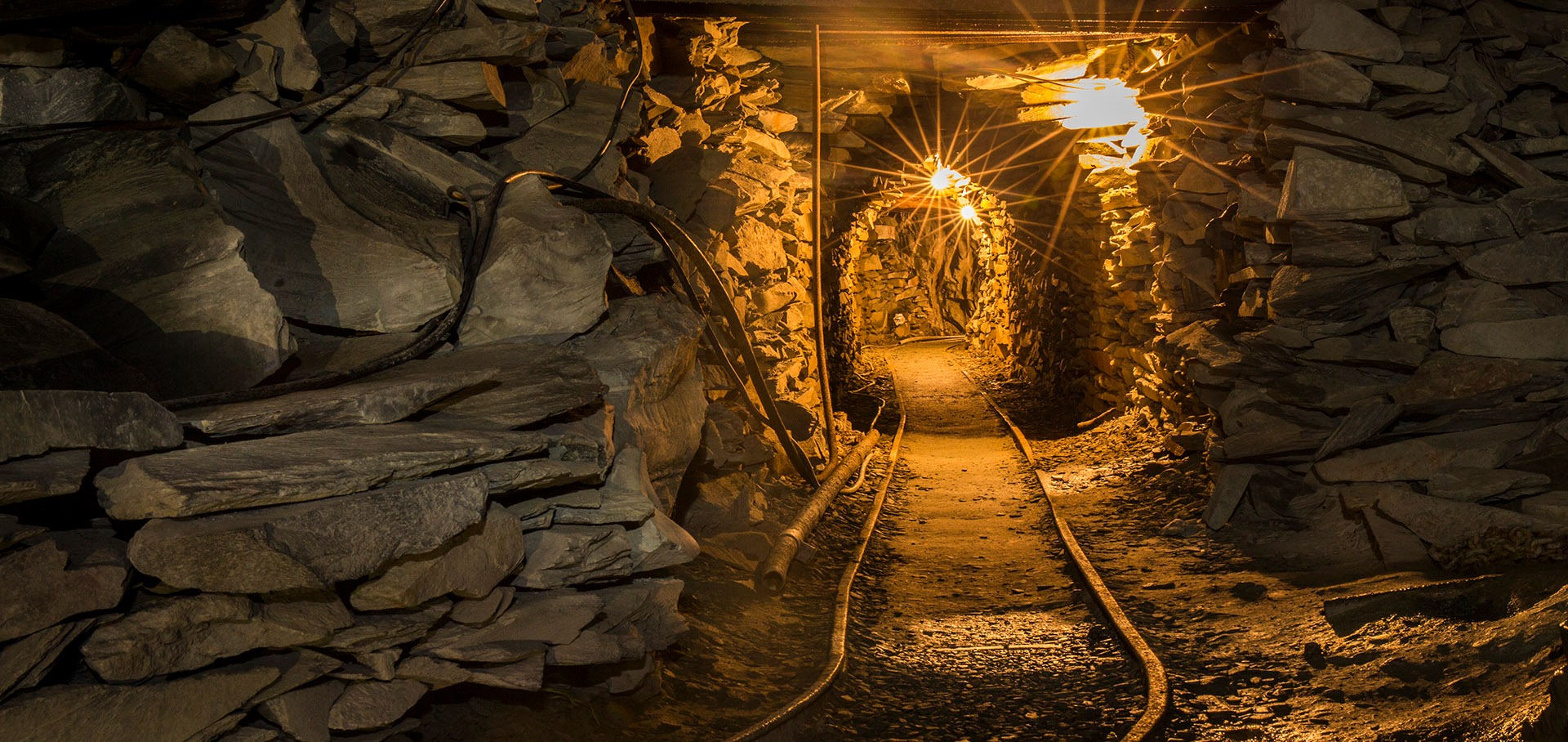
Picture this: deep beneath the earth's surface, in the labyrinthine tunnels of an Australian coal mine, a continuous ballet of heavy machinery unfolds around the clock. Shuttle cars race back and forth like underground taxis, boggers scoop and dump with mechanical precision, and loaders navigate tight spaces with their precious cargo. All of this activity depends on one critical component that often goes unnoticed—the flexible trailing cables that feed power to these vital machines.
Underground mining presents unique challenges that surface operations simply don't face. The environment is harsh, confined, and unforgiving. Temperatures fluctuate, humidity levels soar, and equipment operates in conditions where a single electrical failure can bring an entire operation to a standstill. This is where Type 2S individually screened mining cables earn their reputation as the unsung heroes of the mining industry.
These specialised cables serve as the electrical lifelines for mobile mining equipment, delivering reliable power while withstanding the mechanical stresses, chemical exposures, and environmental extremes that would destroy ordinary electrical cables within days. For mine engineers, operators, safety inspectors, and students entering this field, understanding these cables isn't just technical knowledge—it's essential for maintaining safe, efficient, and profitable mining operations.
The Type 2S cable represents decades of engineering evolution, specifically designed to meet the demanding requirements of Australian mining standards while providing the flexibility and durability that underground mobile equipment demands. Whether powering a shuttle car's drive motors or providing control signals to a sophisticated longwall system, these cables form the critical link between electrical power systems and the machines that extract Australia's mineral wealth.
The Language of the Underground: Mining Machines and Their Unique Terminology
Walk into any Australian mine site, and you'll quickly discover that the underground world has its own vocabulary. The machines that keep operations running aren't just called by their technical names—they've earned colloquial terms that reflect their function and the culture of the people who work with them daily.
The "shuttle" refers to shuttle cars, the workhorses of underground coal transport. These low-profile, rubber-tyred vehicles are essentially underground dump trucks designed to navigate the confined spaces of mine tunnels. A typical shuttle operates in a continuous cycle: it positions itself under a continuous miner or at a loading point, receives its load of coal or ore, then "shuttles" to a discharge point such as a feeder breaker or conveyor system. The shuttle's operation demands cables that can handle constant reeling and unreeling as the machine moves back and forth through its designated route.
The "bogger" is mining slang for load-haul-dump (LHD) vehicles, particularly common in hard rock mining operations. These versatile machines combine the functions of a front-end loader and a haul truck, scooping material with their front bucket, carrying it through mine tunnels, and dumping it at designated locations. The term "bogger" likely derives from the machine's ability to "bog in" and dig, reflecting the straightforward, no-nonsense approach that characterises much of mining terminology. During operation, a bogger's trailing cable experiences extreme flexing as the machine articulates its steering and raises and lowers its bucket.
The "scoop" represents another category of underground loading equipment, typically referring to various types of scooping devices used in smaller-scale operations or specialised applications. These machines often work in tight quarters where larger equipment can't operate effectively, requiring cables that can bend and flex in confined spaces without compromising their electrical integrity.
In a typical Australian underground coal mine, you might witness this scene: the bogger operator, known as a "bogger driver," guides his machine through a freshly blasted heading, its trailing cable snaking behind as it follows the machine's path. The cable reels out from a substantial drum, managing the continuous feed of power while the bogger loads broken coal. Meanwhile, nearby, a shuttle waits at the loading point, its own cable system managing the electrical demands of hydraulic pumps, drive motors, and control systems.
The relationship between these machines and their cables represents a partnership that must function flawlessly under extreme conditions. The cables don't just provide power—they enable the mobility that makes these machines valuable. Without reliable, flexible trailing cables, these mobile workhorses would be tethered to fixed positions, fundamentally changing the nature of underground mining operations.


Understanding Cable Classifications and Electrical Specifications
The Type 2S designation represents a specific category of mining cable engineered to meet the stringent requirements of underground mobile equipment. The classification system reflects both the cable's construction characteristics and its intended application within the broader mining electrical infrastructure.
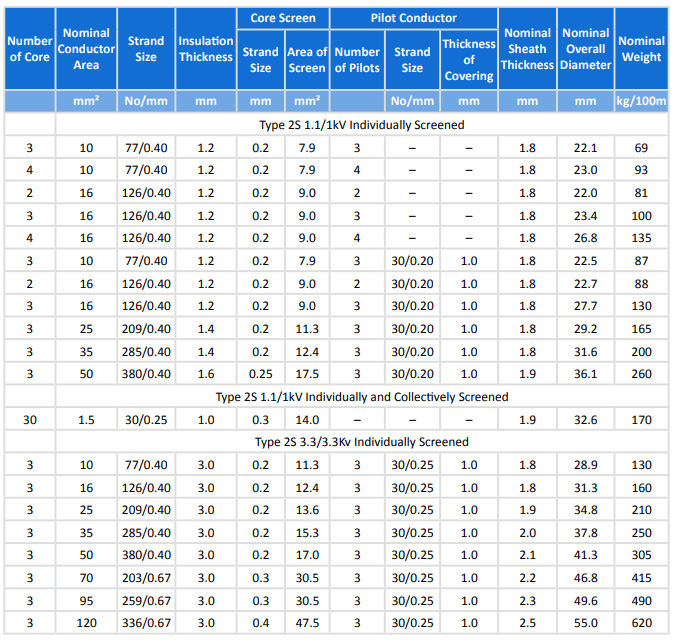
Type 2S cables are manufactured in two primary voltage ratings: 1.1/1.1 kV and 3.3/3.3 kV configurations. The dual voltage notation indicates both the nominal voltage between conductors and the voltage between any conductor and earth. This specification is crucial for mining applications where earth fault protection is not just important—it's mandatory for operator safety and regulatory compliance.
The 1.1/1.1 kV rating serves the majority of mobile mining equipment, providing sufficient voltage for electric drive motors, hydraulic pumps, lighting systems, and control circuits typically found on shuttle cars, boggers, and smaller scoops. This voltage level represents an optimal balance between power transmission capability and safety considerations in the underground environment.
The 3.3/3.3 kV variant caters to higher-power applications, often found on larger mining equipment or systems requiring greater power transmission over longer distances. These higher-voltage cables might power substantial longwall equipment, large conveyor drives, or major ventilation systems where the increased voltage allows for more efficient power transmission and reduced current levels.
The cables comply with a comprehensive suite of Australian and New Zealand standards that govern their design, construction, and performance. AS/NZS 1972:2006 establishes the fundamental requirements for mining cables, ensuring they meet the specific needs of underground environments. AS/NZS 1125 provides additional specifications for flexible cables used on mobile mining equipment, while AS/NZS 3808 addresses the broader electrical safety requirements for mining installations.
These standards don't just specify electrical characteristics—they mandate performance requirements that address the unique challenges of underground mining. The cables must maintain their electrical integrity while subjected to continuous flexing, temperature variations from -25°C to +90°C, exposure to mine gases and dust, mechanical abrasion, and occasional impact from mining equipment.
The electrical characteristics of Type 2S cables extend beyond simple power transmission. Many configurations include pilot cores or control cores that serve critical safety functions. These additional conductors enable continuous monitoring of cable integrity, providing early warning of potential failures before they become dangerous. The pilot core system can detect loss of earth continuity or insulation breakdown, triggering automatic shutdown systems that protect both equipment and personnel.
For mine electrical engineers, understanding these specifications translates directly to operational decisions. The choice between 1.1 kV and 3.3 kV systems affects not just cable selection but also the design of motor control centers, protection systems, and maintenance procedures. The higher voltage systems offer advantages in power transmission efficiency but require more sophisticated protection systems and maintenance protocols.

Dissecting the Cable: Construction and Engineering Excellence
The construction of a Type 2S mining cable represents a masterpiece of electrical engineering, where every component serves multiple purposes in creating a cable that can survive and thrive in one of the most demanding electrical applications imaginable. Understanding this construction helps explain why these cables command premium prices and why their proper selection and maintenance are so critical to mining operations.
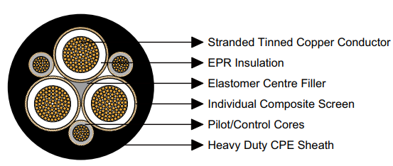
At the heart of every Type 2S cable lies the conductor system: stranded tinned annealed copper conductors that provide the pathway for electrical current. The stranded construction offers crucial flexibility compared to solid conductors, allowing the cable to bend and flex through countless cycles without conductor fatigue. The tinning process applies a thin layer of tin to each copper strand, providing corrosion resistance and ensuring reliable electrical connections even in the moist, chemically aggressive environment of underground mines.
The conductor stranding follows precise specifications that balance flexibility with current-carrying capacity. For example, a 16 mm² conductor typically uses 126 strands of 0.40 mm diameter wire, creating a conductor that can flex repeatedly while maintaining its electrical integrity. This stranding pattern distributes mechanical stress across multiple small wires rather than concentrating it in a few large strands, significantly extending the cable's flex life.
Surrounding each conductor is EPR (Ethylene Propylene Rubber) insulation, a synthetic rubber compound chosen specifically for its electrical properties and environmental resistance. EPR maintains its insulating properties across the wide temperature range encountered in mining applications, from the near-freezing conditions of some underground areas to the elevated temperatures generated by electrical equipment and ambient mine heat. The insulation thickness varies with voltage rating: 1.2 mm for 1.1 kV applications and 3.0 mm for 3.3 kV systems, providing appropriate dielectric strength for each voltage level.
The cable core assembly includes an elastomer centre filler that maintains the cable's round cross-section and provides additional mechanical support. This filler material contributes to the cable's flexibility while ensuring that the individual conductors maintain their relative positions during flexing. Without proper core filling, cables would develop flat spots and internal stress concentrations that could lead to premature failure.
Many Type 2S configurations include pilot and control cores alongside the main power conductors. These smaller conductors, typically using 30 strands of 0.20 mm or 0.25 mm wire, serve critical monitoring and control functions. The pilot cores are individually insulated with EPR and may include their own screening for enhanced signal integrity. These cores enable continuous monitoring of cable condition and provide pathways for control signals that operate equipment functions.
The individual screening system represents one of the most sophisticated aspects of Type 2S cable construction. Each power conductor receives its own composite screen consisting of tinned annealed copper braiding interwoven with polyester yarn. This screening system serves multiple critical functions: it provides a path for earth fault currents, creates electromagnetic shielding to prevent interference with control systems, and enables continuous monitoring of insulation integrity.
The copper braiding alone would provide excellent electrical performance, but the addition of polyester yarn transforms the screen into a composite structure that can withstand the mechanical stresses of continuous flexing. The polyester provides tensile strength and prevents the copper braid from distorting under mechanical stress, ensuring that the screen maintains its electrical continuity throughout the cable's operational life.
The outer sheath represents the cable's first line of defence against the harsh mining environment. Type 2S cables utilise heavy-duty CPE (Chlorinated Polyethylene) sheathing, a material specifically chosen for its exceptional resistance to oil, chemicals, abrasion, and tearing. CPE maintains its flexibility across the required temperature range while providing excellent resistance to the various fluids and chemicals encountered in mining operations.
The sheath thickness varies with cable size and application, typically ranging from 1.8 mm for smaller cables to over 2.5 mm for larger, higher-voltage variants. This substantial sheath thickness provides mechanical protection while maintaining the flexibility essential for trailing cable applications.


Physical Specifications and Performance Characteristics
The physical dimensions and performance characteristics of Type 2S mining cables reflect the careful balance between electrical capability, mechanical durability, and practical handling requirements that define successful mining cable design. These specifications directly impact equipment selection, installation procedures, and operational performance in underground mining applications.
Consider a typical 3-core, 16 mm² Type 2S cable rated for 1.1/1.1 kV service with pilot cores. This configuration, commonly used on shuttle cars and smaller boggers, measures approximately 27.7 mm in overall diameter and weighs about 130 kg per 100-metre length. While these dimensions might seem substantial compared to surface electrical cables, they represent optimal sizing for the demanding requirements of underground mobile equipment.
The weight consideration becomes crucial when specifying cable reeling systems. A 500-metre reel of this cable configuration weighs approximately 650 kg, requiring substantial mechanical support and powerful reeling mechanisms. Mine engineers must account for these weights when designing cable handling systems and specifying the structural supports needed for proper cable management.
For higher-power applications, the 3.3/3.3 kV variants present even more substantial physical characteristics. A 3-core, 35 mm² cable in this voltage class measures approximately 37.8 mm in diameter and weighs 250 kg per 100 metres. The increased insulation thickness required for higher voltage operation contributes significantly to both diameter and weight, impacting handling procedures and equipment requirements.
The thermal performance characteristics of Type 2S cables define their current-carrying capabilities and operational limits. The cables are designed to operate continuously with conductor temperatures up to 90°C, with EPR insulation maintaining its integrity even under these elevated temperature conditions. This thermal rating enables the cables to carry substantial currents while maintaining adequate safety margins.
The flexible temperature range extends from -25°C to +90°C, covering the environmental extremes encountered in mining operations. The lower temperature limit addresses the conditions found in some deep mines or during winter surface handling, while the upper limit accounts for the heat generated by electrical equipment and ambient mine temperatures. This wide temperature range ensures reliable operation regardless of seasonal variations or specific mine conditions.
Mechanical flexibility represents perhaps the most critical performance characteristic for trailing cable applications. Type 2S cables maintain their flexibility even at low temperatures, ensuring that equipment can operate reliably regardless of environmental conditions. The minimum bend radius specification typically equals 7.5 times the cable diameter when the cable is subjected to continuous flexing, providing guidance for cable routing and handling procedures.
The electrical characteristics extend beyond simple power transmission to include the sophisticated monitoring capabilities enabled by the screening and pilot core systems. The composite screening system provides path resistance specifications that ensure adequate earth fault protection, typically maintaining screen resistance below specified limits that enable reliable operation of earth fault monitoring systems.
Pilot core resistance specifications, typically ranging from 3 to 5.5 ohms per 100 metres depending on the core cross-section, ensure adequate signal transmission for monitoring and control functions. These specifications enable the pilot monitoring systems to detect cable faults and insulation degradation before they become dangerous, providing an essential safety margin in underground operations.
The cables' resistance to various environmental factors reflects their specialised construction. CPE sheathing provides excellent resistance to oils, hydraulic fluids, and various chemicals commonly encountered in mining operations. The sheath also resists abrasion and cutting, protecting the internal cable components from the mechanical hazards present in underground environments.
Installation Best Practices and Professional Guidelines
Proper installation of Type 2S mining cables requires understanding that goes far beyond basic electrical connections. The unique demands of underground mobile equipment create installation challenges that require specialised knowledge, appropriate equipment, and careful attention to details that might seem minor but can determine the difference between reliable operation and premature failure.
The reeling and trailing systems that manage these cables represent sophisticated mechanical installations in their own right. Cable reels must be sized not just for the cable's physical dimensions but also for the dynamic loads created by the starting and stopping of heavy mining equipment. The reel drum diameter should exceed 20 times the cable diameter to prevent excessive bending stress during reeling operations. This specification often requires substantial reel assemblies that can accommodate the large drums necessary for proper cable management.
The minimum bend radius requirements become critical during installation and operation. When Type 2S cables are subjected to continuous flexing, as occurs in trailing applications, the bend radius must not be less than 7.5 times the cable diameter. For a 35 mm diameter cable, this translates to a minimum bend radius of approximately 260 mm under dynamic conditions. Tighter bends might not cause immediate failure but will significantly reduce cable life through gradual conductor fatigue and insulation degradation.
Cable routing in underground environments requires careful consideration of the physical hazards present in mine tunnels. Sharp edges, protruding rock formations, and equipment traffic patterns all pose threats to cable integrity. Successful installations incorporate cable guides, protective channels, and routing systems that minimise exposure to these hazards while maintaining the flexibility necessary for equipment operation.
In bogger applications, the cable routing must accommodate the machine's articulated steering system and the vertical movement of the loading bucket. The cable support system should include swivel connections that allow the cable to follow the machine's movements without creating twist or excessive stress concentrations. Many successful installations incorporate cable guides that maintain proper cable positioning while allowing for the full range of equipment movement.
Shuttle car installations present different challenges, with cables that must reel out smoothly during the car's travel between loading and dumping points. The cable often passes over or near other equipment, requiring protection systems that prevent damage from contact with conveyor structures, roof supports, or other machinery. Cable rollers positioned near feeder breakers and other fixed equipment help reduce wear and ensure smooth cable movement.
The electrical connections themselves demand specialised techniques and materials designed for the mining environment. Cable terminations must provide not only reliable electrical connections but also mechanical support that can handle the forces transmitted through the cable during equipment operation. Mining-rated connectors often incorporate strain relief systems that prevent the electrical connections from carrying mechanical loads that could cause connection failure.
Ground-checking circuits enabled by the cable's screening and pilot core systems require proper configuration during installation. These monitoring systems provide continuous verification of earth continuity and cable integrity, but they must be correctly connected and calibrated to provide reliable protection. The screen connections must provide low-resistance paths to the mining equipment's grounding system, while pilot core connections must interface properly with the ground-checking relays and monitoring equipment.
Environmental protection during installation extends beyond the cable itself to include the termination enclosures and connection hardware. Underground environments subject electrical connections to moisture, dust, and various chemicals that can cause corrosion and connection degradation. Proper sealing of termination enclosures and the use of appropriate gaskets and protective compounds help ensure long-term reliability.
Site-specific considerations often determine the success or failure of cable installations. In narrow tunnel applications, cable routing might require specialised support systems that maintain adequate clearances while providing necessary protection. Areas with heavy equipment traffic might require additional cable protection or alternative routing strategies that avoid high-risk zones.
The testing and commissioning procedures for Type 2S cable installations must verify both the electrical integrity and the mechanical installation quality. Insulation resistance testing confirms that the cable's electrical characteristics meet specifications, while continuity testing verifies proper connection of power conductors, screens, and pilot cores. Mechanical testing should confirm that the cable can move through its full range of operation without excessive stress or interference with other mine systems.
Troubleshooting Guide: Common Issues and Professional Solutions
Understanding the common problems that affect Type 2S mining cables and their solutions represents essential knowledge for mining professionals responsible for maintaining reliable electrical systems. The harsh conditions and demanding applications create specific failure modes that require targeted diagnostic and repair strategies.
Question: The pilot core monitoring system indicates a fault, but there's no apparent damage to the main cable. Why has the machine shut down when the power circuits seem intact?
This scenario represents one of the most common and initially confusing situations encountered with Type 2S cables. The answer lies in understanding the sophisticated safety systems built into modern mining electrical installations. The pilot core system provides continuous monitoring of cable integrity, detecting problems before they become dangerous. When the pilot core circuit is broken, lost, or shows excessive resistance, the ground-checking relay interprets this as a potential safety hazard and initiates an automatic shutdown.
The solution requires systematic diagnosis of the pilot circuit integrity. Begin by measuring the pilot core resistance from the machine end, comparing the results to the cable's specifications. A 16 mm² cable with pilot cores should typically show pilot resistance between 3 and 5.5 ohms per 100 metres. Significantly higher readings indicate pilot core damage, while infinite resistance suggests a complete break.
If the pilot core shows damage, examine the cable screening system, as pilot core and screen damage often occur together due to their similar construction. The screen provides the earth fault protection path, and damage to this system creates genuine safety concerns that justify the automatic shutdown. Temporary repairs might involve splicing the pilot core, but permanent solutions typically require cable replacement or professional cable repair services.
Question: The cable jacket shows significant abrasion and damage near the equipment connection point, particularly around wheel chocks and cable guides. What causes this localised wear, and how can it be prevented?
This wear pattern typically results from improper cable management that allows the cable to move against fixed surfaces during equipment operation. As mobile equipment moves, the cable must flex and adjust position, but if the cable routing forces it to rub against wheel chocks, frame members, or inadequate cable guides, rapid wear occurs at these contact points.
The immediate solution involves installing proper wear protection at the damage location. Spiral cable protectors, split-loom tubing, or specialised wear sleeves can provide temporary protection, but the underlying routing problem must be addressed to prevent recurring damage. Professional assessment of the cable routing system often reveals that the cable guides are improperly positioned, inadequately sized, or missing entirely.
Long-term prevention requires redesigning the cable support system to eliminate contact between the cable and fixed surfaces during normal equipment operation. This might involve relocating cable guides, installing additional support points, or modifying the equipment's cable attachment point to provide better strain relief. The investment in proper cable management systems pays dividends through extended cable life and reduced maintenance costs.
Question: Earth leakage monitoring systems show increasing leakage current, but visual inspection reveals no obvious cable damage. Should the cable be replaced immediately, or can operation continue?
Increasing earth leakage current indicates deteriorating insulation integrity, often caused by moisture ingress, chemical exposure, or gradual insulation degradation. This condition represents a progressive safety hazard that will eventually result in earth fault protection operation or, in worst-case scenarios, dangerous fault conditions.
The appropriate response depends on the severity of the leakage and the rate of increase. Australian mining electrical standards specify maximum permissible earth leakage currents, and operation should not continue if these limits are exceeded. Even within acceptable limits, steadily increasing leakage current indicates a cable approaching the end of its useful life.
Professional cable testing can provide more detailed information about insulation condition. Insulation resistance testing, conducted with appropriate high-voltage test equipment, can quantify the insulation deterioration and help predict remaining cable life. If testing reveals insulation resistance below specified minimums, immediate cable replacement is necessary.
Temporary measures might include more frequent monitoring of leakage current levels and preparation for emergency cable replacement. However, the progressive nature of insulation deterioration means that delayed replacement often results in more expensive emergency repairs and potential safety incidents.
Question: During cold weather, the cable becomes stiff and difficult to handle, affecting equipment mobility. The cable is rated for operation at -25°C, so why are we experiencing problems?
While Type 2S cables maintain their electrical integrity at low temperatures, their physical flexibility does decrease as temperatures approach the lower specification limit. At -25°C, the cable will be noticeably stiffer than at normal operating temperatures, potentially affecting the smooth operation of reeling systems and increasing the force required for cable movement.
The solution involves managing both storage and operational procedures to minimise cold weather impacts. Cable stored outdoors should be kept in insulated enclosures or heated storage areas when possible. For cables already deployed, temporary warming using heated air circulation or insulated cable troughs can restore normal flexibility.
Operational procedures should account for reduced cable flexibility during cold weather. Reeling speeds might need to be reduced, and additional care taken during manual cable handling to prevent damage from excessive force. Some operations rotate cable hang-off points periodically during cold weather to prevent permanent set in the cable configuration.
Prevention strategies include selecting cable storage locations that provide protection from extreme temperatures and incorporating heating systems into cable storage and handling facilities in operations where extreme cold is common.
Question: We're experiencing significant voltage drop issues with our longer cable runs, particularly during equipment starting. The cables are properly sized according to current ratings, so what's causing the problem?
Voltage drop in mining cables results from the resistance of the conductors, which increases with temperature and length. While the cables might be properly sized for continuous current rating, the combination of long cable lengths and high starting currents can create voltage drops that affect equipment performance.
The solution requires calculating voltage drop using the cable's resistance specifications at operating temperature, typically 90°C for fully loaded conditions. Type 2S cable specifications provide resistance values that enable accurate voltage drop calculations for specific installations. Starting currents, which can be several times the rated current, must be considered in these calculations.
For installations where voltage drop calculations reveal problems, solutions include upgrading to larger conductor sizes, reducing cable length where possible, or implementing reduced voltage starting systems that limit starting current. In some cases, the installation of intermediate power distribution points can reduce individual cable run lengths and associated voltage drops.
The economic analysis should consider both the cost of cable upgrades and the operational impact of voltage drop problems, including reduced equipment performance and potential damage to motors and control systems from sustained operation at reduced voltage levels.
Conclusion: The Foundation of Reliable Underground Mining Operations
The Type 2S individually screened mining cable represents far more than a simple electrical component—it embodies the engineering excellence and specialised knowledge that enable modern underground mining operations to function safely and efficiently. Through this comprehensive examination, we've explored how these sophisticated cables serve as the critical link between power systems and the mobile equipment that forms the backbone of mineral extraction operations.
The evolution of cable technology from basic power conductors to the sophisticated monitoring and protection systems found in modern Type 2S cables reflects the mining industry's commitment to both operational efficiency and worker safety. The individually screened construction, pilot core monitoring systems, and robust mechanical design create cables capable of withstanding conditions that would destroy conventional electrical cables within days or weeks.
For mining professionals, understanding these cables extends beyond technical specifications to encompass the practical realities of installation, maintenance, and troubleshooting in underground environments. The proper selection, installation, and maintenance of Type 2S cables directly impacts equipment availability, operational safety, and maintenance costs. The investment in quality cable systems and proper installation procedures pays dividends through reduced downtime, extended equipment life, and enhanced safety performance.
The terminology and culture surrounding these applications—from "shuttles" and "boggers" to the specialised installation techniques required for reeling systems—reflects the unique nature of underground mining operations. Success in this environment requires not just technical knowledge but also understanding of the practical constraints and operational requirements that define effective mining electrical systems.
As mining operations continue to evolve toward greater automation and more sophisticated control systems, the importance of reliable cable systems becomes even more critical. The Type 2S cable's capability to provide both power transmission and continuous integrity monitoring positions it well for future mining applications where system reliability and safety monitoring are paramount concerns.
The advances in materials technology, particularly the development of chlorinated polyethylene sheathing and composite screening systems, demonstrate the ongoing innovation in mining cable design. These improvements help mining operations meet increasingly stringent safety requirements while maintaining the operational flexibility essential for efficient mineral extraction.
Looking forward, the principles embodied in Type 2S cable design—individual screening for enhanced monitoring, robust mechanical construction for demanding applications, and comprehensive protection systems for harsh environments—will likely influence the development of future mining electrical systems. As the industry continues to push the boundaries of underground operations, both in depth and in automation sophisticity, the cables that power these operations must continue to evolve to meet new challenges while maintaining the reliability and safety that underground workers depend upon.
The investment in understanding and properly implementing Type 2S cable systems represents an investment in the fundamental infrastructure that enables safe, efficient, and profitable mining operations. For mine engineers, operators, and maintenance professionals, this knowledge forms an essential component of the expertise required to maintain world-class mining operations in Australia's challenging underground environment.

