Type 450 3.3kV to 33kV Mining Cable in Hoist/Winder Applications:
Complete guide to Type 450 mining cables for hoist/winder systems in Australian mines. Covers electrical parameters, installation standards, mechanical specifications, and real-world applications with practical FAQ solutions.
6/17/202519 min read
Type 450 3.3kV to 33kV Mining Cable in Hoist/Winder Applications
The backbone of any successful mining operation lies not just in the heavy machinery that extracts precious resources from the earth, but in the critical infrastructure that powers these systems safely and reliably. Among the most demanding applications in mining is the hoist or winder system, where cables must simultaneously deliver substantial electrical power while withstanding extreme mechanical stresses, environmental challenges, and the constant cycle of reeling and unreeling that defines their operational life.
Type 450 reeling and trailing cables, designed to meet the rigorous demands of Australian mining standards, represent a sophisticated engineering solution specifically crafted for these challenging applications. Understanding how these cables integrate with hoist and winder systems requires a deep appreciation of both the mechanical complexities of mining equipment and the electrical engineering principles that ensure safe, reliable power delivery in one of the world's most demanding industrial environments.
Understanding Hoist and Winder Systems: The Heart of Mining Operations
A hoist, commonly referred to as a "winder" in Australian mining parlance, serves as the crucial vertical transportation system that connects the surface operations with the underground workings. These massive mechanical systems perform the essential task of lifting and lowering personnel, equipment, and extracted materials through mine shafts that can extend hundreds or even thousands of metres below ground level.
The fundamental principle behind these systems involves a large rotating drum or sheave wheel that winds and unwinds steel cables or ropes, with the hoist house typically located at the surface near the shaft head. The engineering challenge becomes immediately apparent when you consider that these systems must operate with absolute reliability, as they literally hold the lives of miners in their mechanical grip while simultaneously handling tonnes of equipment and raw materials.
Two primary configurations dominate the mining industry: drum hoists and friction winders, often called Koepe systems. Drum hoists utilise a large cylindrical drum around which the hoisting cables are wound in multiple layers, creating what miners refer to as "multi-layer spooling." This traditional approach provides excellent control and is particularly suited for deeper shafts where the cable length requires substantial storage capacity.
Friction winders, by contrast, employ a large wheel with grooved surfaces where the hoisting cables pass over the wheel without being wound around it. The lifting force comes from friction between the cables and the wheel surface, with counterweight systems providing balance. This configuration, known as "single-layer" operation, offers advantages in terms of speed and efficiency, particularly for high-capacity operations.
The role of electrical cables in these systems extends far beyond simple power delivery. These cables must provide reliable electrical connections to the hoist motors, control systems, and safety equipment while enduring the constant mechanical stress of being wound and unwound thousands of times throughout their service life. The cables face unique challenges including dynamic bending stresses, abrasion against drum surfaces, exposure to mining environments, and the need to maintain electrical integrity under conditions that would quickly destroy conventional electrical cables.


Electrical Parameters and Engineering Specifications of Type 450 Cables
The Type 450 cable series represents a carefully engineered solution designed specifically for the demanding requirements of mining hoist applications. These cables are available across a comprehensive voltage range from 3.3kV to 33kV, allowing mining operations to select the appropriate voltage class based on their specific power requirements and system configurations.
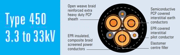
The fundamental electrical architecture of Type 450 cables follows a sophisticated multi-conductor design that addresses both power transmission and safety monitoring requirements. The cable incorporates three main power conductors constructed from flexible stranded tinned annealed copper, providing the primary electrical pathways for three-phase power distribution to hoist motors and associated equipment.
Beyond the primary power conductors, the cable integrates two interstitial earth conductors, which serve crucial safety functions by providing reliable earth fault protection and ensuring that any electrical faults are immediately detected and safely managed. These earth conductors, constructed with CSP (Copper Screened Polymer) covering over flexible stranded tinned copper, maintain their integrity even under the severe mechanical stresses encountered in hoist applications.
The inclusion of a dedicated pilot conductor represents another critical aspect of the cable's design philosophy. This EPR-insulated conductor serves as a monitoring and control pathway, enabling continuous assessment of cable integrity and providing communication channels for safety systems. In practical mining operations, this pilot conductor often carries signals from proximity sensors, emergency stop systems, and other critical safety devices.
The conductor construction itself deserves particular attention, as it directly impacts both electrical performance and mechanical durability. The use of tinned annealed copper provides excellent conductivity while the tinning process offers superior corrosion resistance in mining environments where moisture, chemicals, and abrasive particles are commonplace. The flexible stranded construction ensures that the conductors can withstand the repeated bending cycles inherent in hoist operations without suffering from fatigue failure.
Insulation technology in Type 450 cables employs EPR (Ethylene Propylene Rubber), a material specifically chosen for its exceptional electrical properties and mechanical durability. EPR provides excellent dielectric strength, maintaining insulation integrity across the full voltage range while offering superior resistance to thermal cycling, mechanical stress, and environmental degradation. The insulation thickness varies according to voltage class, with higher voltage cables incorporating correspondingly thicker insulation layers to maintain appropriate safety margins.
The screening system represents one of the most sophisticated aspects of Type 450 cable design. Conductor screens, constructed from semiconductive compounds, ensure uniform electric field distribution around each conductor, preventing corona discharge and localised stress concentrations that could lead to premature failure. For cables rated at 3.3kV and above, these conductor screens become mandatory components, highlighting their critical role in high-voltage applications.
Insulation screens, fabricated from semiconductive elastomer materials, provide additional field control while facilitating the detection of insulation faults. The composite screen system combines tinned annealed copper braiding interwoven with polyester yarn, creating a robust electromagnetic shield that protects against interference while providing mechanical protection. This composite construction is then covered with semiconductive tape, creating a comprehensive screening system that addresses both electrical and mechanical requirements.
The cable's compliance with Australian and New Zealand standards including AS/NZS 2802:2000, AS/NZS 1125, AS/NZS 3808, and AS/NZS 5000.1 ensures that Type 450 cables meet the rigorous safety and performance requirements mandated for mining applications. These standards address everything from conductor construction and insulation requirements to testing protocols and installation practices, providing a comprehensive framework for safe and reliable operation.


Mechanical Installation Considerations for Hoist and Winder Applications
The installation of Type 450 cables in hoist and winder systems presents unique mechanical challenges that require careful consideration of cable routing, support systems, and operational parameters. The installation process begins with a thorough understanding of the specific hoist configuration, including drum dimensions, winding patterns, and operational characteristics.
In drum hoist installations, the cable routing typically follows a path from the electrical supply point, through a series of guide pulleys and support structures, before being anchored to the drum surface. The cable then winds around the drum in carefully controlled layers, with each successive layer building upon the previous one. This multi-layer spooling arrangement requires precise control of cable tension and positioning to prevent crossovers, gaps, or other irregularities that could cause mechanical damage during operation.
The concept of bend radius becomes critically important in hoist applications, as the cable must conform to the curvature of the drum while maintaining its electrical and mechanical integrity. Industry practice typically specifies minimum bend radii of approximately twelve times the cable's overall diameter, though this can vary based on specific cable construction and operational requirements. Violating these minimum bend radius requirements can lead to conductor damage, insulation failure, or premature cable failure.
Cable anchoring systems must be designed to transfer the substantial mechanical loads encountered during hoist operation while protecting the cable from damage at the attachment point. These anchoring systems typically incorporate strain relief mechanisms that distribute mechanical stresses over an extended length of cable, preventing stress concentration at the anchor point that could lead to conductor breakage or insulation damage.
Slack control represents another critical aspect of cable installation, particularly in applications where the hoist operates with varying loads or in situations where cable length changes due to thermal expansion or mechanical settling. Proper slack control systems ensure that the cable maintains appropriate tension throughout its operational range while preventing excessive slack that could lead to cable damage or operational problems.
The installation process requires careful attention to cable support throughout its routing path, with particular emphasis on areas where the cable transitions between different support structures or changes direction. Guide pulleys must be appropriately sized and positioned to maintain minimum bend radius requirements while providing smooth cable movement during operation.
Safety checks during installation encompass both electrical and mechanical verification procedures. Insulation integrity testing ensures that the cable's electrical performance meets specification requirements, while earth continuity testing verifies the proper operation of safety systems. Mechanical inspections focus on identifying any damage that may have occurred during installation, including conductor deformation, sheath damage, or improper cable positioning.
Mining Terminology and On-Site Language Practices
The language used on Australian mining sites reflects decades of operational experience and cultural development, with specific terminology that carries important technical and safety implications. Understanding this language is essential for anyone working with hoist and winder systems, as miscommunication can have serious consequences in these safety-critical applications.
The terms "winder" and "drum" are often used interchangeably in casual conversation, though they technically refer to different components of the hoist system. A "winder" encompasses the entire hoist mechanism, including the drum, motor, brake systems, and control equipment, while the "drum" specifically refers to the cylindrical component around which the cables are wound. In practice, you'll hear miners say they're "working the winder" when they're performing maintenance on any component of the hoist system, or "checking the drum" when they're specifically inspecting the cable winding mechanism.
The phrase "pulling cable on the drum" has become standard terminology for the process of installing or replacing cables on hoist systems. This expression captures both the physical effort involved in cable installation and the mechanical process of drawing the cable into position around the drum. Experienced crews often refer to "snaking the cable," particularly when routing cables through complex paths or around obstacles, a term that vividly describes the careful, methodical process required to avoid damage during installation.
Regional variations in terminology reflect the diverse backgrounds of Australian mining personnel and the influence of different mining companies and equipment manufacturers. Some operations refer to the process of cable installation as "stringing the drum," while others use "laying cable," each term carrying slightly different connotations about the specific techniques and procedures involved.
The concept of "multi-layer spooling" represents a technical term that has found its way into everyday mining vocabulary, reflecting the importance of proper cable winding techniques in hoist operations. Miners frequently discuss "keeping the layers tight" or "watching for crossovers," terminology that reflects their understanding of the mechanical principles underlying successful cable installation.
Safety-related terminology carries particular importance in mining environments, where clear communication can be a matter of life and death. Terms like "dead rope" and "live rope" clearly distinguish between cables that are electrically energised and those that are not, while "locked out" and "tagged out" refer to safety procedures that prevent accidental energisation during maintenance activities.
Detailed Product Structure and Component Analysis
The sophisticated structure of Type 450 cables reflects decades of engineering development focused on meeting the demanding requirements of mining applications. Understanding each component and its role in overall cable performance provides insight into why these cables perform successfully in challenging environments where other cable types would fail.
At the core of each Type 450 cable lie the three main power conductors, constructed from flexible stranded tinned annealed copper. The conductor construction varies significantly across different cable sizes, with smaller cables utilising finer strand configurations while larger cables employ thicker individual strands to achieve the required cross-sectional area. For example, a 16mm² conductor might utilise 126 strands of 0.40mm wire, while a 300mm² conductor could employ 854 strands of 0.67mm wire, demonstrating how conductor construction adapts to meet both electrical and mechanical requirements.
The tinning process applied to these copper conductors serves multiple purposes beyond simple corrosion protection. The tin coating provides a barrier against oxidation that could increase conductor resistance over time, while also facilitating superior connections during cable termination. In mining environments where cables may be exposed to moisture, chemicals, or other corrosive substances, this protection becomes essential for maintaining long-term performance.
Surrounding each conductor, the conductor screen creates a controlled electrical environment that prevents corona discharge and ensures uniform electric field distribution. This semiconductive compound layer becomes increasingly important as voltage levels rise, with cables rated for 3.3kV and above incorporating mandatory conductor screens. The thickness and composition of these screens are carefully engineered to provide appropriate electrical performance while maintaining mechanical flexibility.
The EPR insulation system represents the primary electrical barrier between conductors and between conductors and earth. The thickness of this insulation layer increases with voltage rating, ranging from 2.2mm for 3.3kV applications to 10.5mm for 33kV applications. This stepped approach ensures appropriate insulation coordination while minimising cable diameter and weight where possible.
The insulation screen, constructed from semiconductive elastomer, provides additional electric field control while facilitating fault detection. This screen helps contain the electric field within the insulation system while providing a conductive path that ensures rapid fault clearing in the event of insulation failure.
The composite screen system represents one of the most innovative aspects of Type 450 cable design. This system combines tinned annealed copper braiding with polyester yarn reinforcement, creating a screen that provides both electromagnetic shielding and mechanical protection. The copper braiding offers excellent electrical conductivity for fault current paths and electromagnetic interference suppression, while the polyester yarn provides mechanical reinforcement that helps the screen withstand the flexing and abrasion encountered in hoist applications.
The elastomer centre filler serves multiple functions within the cable structure, providing mechanical support for the conductor assembly while filling void spaces that could otherwise allow conductor movement during operation. This filler material maintains cable geometry under mechanical stress while providing additional protection against moisture ingress.
The two interstitial earth conductors integrate seamlessly into the cable structure, providing redundant earth fault protection without significantly increasing cable diameter. These conductors, with their CSP covering over flexible stranded tinned copper construction, maintain their electrical integrity even under severe mechanical stress.
The interstitial pilot conductor, with its dedicated EPR insulation, provides monitoring and control capabilities that are essential for modern mining operations. This conductor often carries signals from safety systems, position sensors, and communication equipment, making its reliable operation crucial for overall system safety.
The textile reinforcement layer provides mechanical protection for the cable core while distributing stress loads across the cable structure. This open-weave braid construction allows for cable flexibility while providing significant resistance to mechanical damage from external sources.
The outer sheath system represents the cable's primary defence against environmental hazards. The extra-heavy duty PCP (Polychloroprene) sheath provides excellent resistance to oils, chemicals, abrasion, and weather exposure. Alternative CSP (Chlorosulfonated Polyethylene) sheath options offer enhanced chemical resistance for specific applications, though PCP remains the standard choice for most mining applications due to its superior mechanical properties.

Real-World Case Study: Implementation in a Typical Australian Mining Operation
To illustrate the practical application of Type 450 cables in mining operations, consider a typical underground gold mine in Western Australia utilising a drum hoist system for personnel and material transport. The mine shaft extends 800 metres below surface, requiring a hoist system capable of handling 2-tonne loads at speeds up to 8 metres per second.
The hoist installation features a 4-metre diameter drum driven by a 750kW three-phase motor operating at 11kV. The electrical supply system requires cables capable of delivering power reliably while withstanding the mechanical stresses of constant reeling and unreeling operations. After careful analysis of system requirements, the mine selected Type 450.11 cable with 120mm² conductors, providing adequate current carrying capacity while maintaining acceptable voltage drop characteristics.
The installation process began with careful measurement and calculation of cable lengths, accounting for the drum circumference, number of layers required, and additional length needed for connections and strain relief. The crew determined that approximately 950 metres of cable would be required, including generous allowances for terminations and emergency repairs.
Cable routing started at the main electrical switchroom, where the cable connects to the 11kV supply through appropriate switching and protection equipment. From this point, the cable follows a carefully planned path through the hoist house, supported by custom-designed cable trays and guide systems that maintain minimum bend radius requirements throughout the installation.
The critical phase of installation involved anchoring the cable to the drum and beginning the winding process. The crew used specialised cable pulling equipment to maintain consistent tension while carefully controlling the cable position to ensure uniform layer formation. Throughout this process, they paid careful attention to avoiding cable crossovers or gaps that could cause mechanical damage during operation.
During the installation, experienced crew members frequently used mining terminology that reflected both their technical understanding and their practical experience. Comments like "keep that cable tight on the drum" and "watch for any twisting as we pull" demonstrated their awareness of the mechanical principles underlying successful cable installation. When routing the cable around a particularly tight corner, one crew member noted that they had to "snake it around the pulley system," using terminology that vividly described the careful manipulation required.
The completed installation underwent comprehensive testing including insulation resistance measurements, earth continuity verification, and mechanical inspection of all cable support systems. The pilot conductor was connected to the mine's safety monitoring system, providing continuous assessment of cable integrity during operation.
Six months after installation, the cable has demonstrated excellent performance characteristics with no electrical faults or mechanical problems. Regular inspection procedures, including visual examination of exposed cable sections and electrical testing of insulation systems, have confirmed that the cable continues to meet all performance requirements despite the demanding operational environment.
Frequently Asked Questions: Addressing Common Challenges and Solutions
Question 1: Why should we choose Type 450 over Type 455 cables for our hoist application?
The primary distinction between Type 450 and Type 455 cables lies in their sheath construction and resulting environmental performance characteristics. Type 450 cables utilise PCP (Polychloroprene) sheathing as standard, which provides excellent mechanical properties, good chemical resistance, and superior performance in typical mining environments. The PCP sheath offers outstanding resistance to oils, moderate chemicals, and physical abrasion while maintaining flexibility across a wide temperature range.
Type 455 cables, by contrast, typically employ CSP (Chlorosulfonated Polyethylene) sheathing, which offers enhanced chemical resistance but with some trade-offs in mechanical properties. CSP provides superior resistance to strong acids, alkalis, and oxidising chemicals, making it the preferred choice in applications where chemical exposure represents the primary environmental challenge.
For most hoist and winder applications, Type 450 cables with PCP sheathing provide the optimal balance of mechanical durability, environmental resistance, and cost-effectiveness. The decision should ultimately be based on a careful analysis of the specific environmental conditions in your operation, with particular attention to the types of chemicals, temperatures, and mechanical stresses the cable will encounter.
Question 2: What is the minimum bending radius requirement for Type 450 cables when installed on hoist drums?
The minimum bending radius for Type 450 cables typically equals twelve times the cable's overall diameter, though this can vary based on specific installation conditions and manufacturer recommendations. This requirement reflects the need to prevent conductor damage, insulation stress, and premature cable failure that can result from excessive bending.
For practical application, a Type 450.11 cable with 120mm² conductors has an overall diameter of approximately 81.6mm, requiring a minimum bend radius of approximately 980mm. This means that hoist drums should have a radius of at least 980mm, though larger radii are preferable for optimal cable life.
It's important to understand that this minimum bend radius applies not only to the drum itself but to all points in the cable installation where bending occurs. Guide pulleys, cable entry points, and transition areas must all maintain these minimum radius requirements to prevent cable damage.
Violating minimum bend radius requirements can lead to several problems including conductor strand breakage, insulation delamination, screen discontinuity, and accelerated cable aging. In extreme cases, severe bending can cause immediate cable failure with potentially catastrophic consequences in mining applications.
Question 3: How can we detect sheath abrasion early before it becomes a serious problem?
Early detection of sheath abrasion requires a combination of visual inspection procedures and electrical testing protocols implemented as part of regular maintenance programs. Visual inspection should focus on areas where the cable contacts the drum surface, guide pulleys, or other mechanical components, looking for signs of sheath wear, scoring, or discoloration that might indicate developing problems.
The most effective electrical test for detecting early sheath deterioration is insulation resistance testing, which can identify moisture ingress or contamination before it reaches levels that cause operational problems. This testing should be performed between conductors and between conductors and earth, with results compared to baseline measurements taken when the cable was new.
Advanced diagnostic techniques including partial discharge testing and time domain reflectometry can provide additional insight into cable condition, though these methods typically require specialised equipment and expertise. For most mining operations, regular visual inspection combined with routine insulation resistance testing provides adequate early warning of developing problems.
Establishing inspection schedules based on operational intensity represents a practical approach to early problem detection. Cables in high-usage applications may require daily visual inspection, while those in lighter service might be adequately monitored through weekly or monthly inspection programs.
Question 4: We're experiencing cable twisting and chatter issues during reeling operations. What causes this and how can we address it?
Cable twisting and chatter during reeling operations typically result from improper cable winding techniques, inadequate tension control, or mechanical problems with the hoist system itself. These issues can cause accelerated cable wear, increased mechanical stress, and potential safety hazards that require immediate attention.
Proper layered winding represents the foundation of successful cable installation and operation. Each layer of cable must be wound uniformly with consistent spacing and tension, avoiding crossovers or gaps that can cause mechanical instability. The cable should lay smoothly against the drum surface with each turn positioned properly relative to adjacent turns.
Tension control systems play a crucial role in preventing cable movement and chatter during operation. Insufficient tension allows the cable to move freely on the drum surface, leading to chatter and accelerated wear. Excessive tension, however, can cause conductor damage and premature cable failure. Most successful installations employ tensioning systems that maintain consistent cable tension throughout the operational range.
Mechanical problems with drum surfaces, guide pulleys, or other hoist components can contribute to cable movement and chatter. Worn drum surfaces, damaged pulleys, or misaligned components can cause irregular cable movement that manifests as twisting or chatter during operation.
The solution typically involves a systematic approach starting with careful inspection of cable winding patterns, followed by adjustment of tension control systems and correction of any mechanical problems with hoist components. In some cases, complete cable rewinding may be necessary to establish proper layer formation and eliminate sources of mechanical instability.
Question 5: What happens if the pilot conductor fails, and how can we prevent this?
Pilot conductor failure represents a serious safety concern in mining applications, as this conductor often carries critical safety signals and provides essential monitoring capabilities for earth fault protection systems. When the pilot conductor fails, mining operations may lose the ability to monitor cable integrity, detect earth faults, or communicate with safety systems, potentially creating hazardous conditions.
The immediate consequence of pilot conductor failure depends on how the pilot circuit is configured and monitored. In systems where the pilot conductor provides continuous monitoring signals, its failure should trigger immediate alarms and potentially automatic shutdown of hoist operations. Systems that use the pilot conductor for intermittent communication may not immediately detect the failure, creating a potentially dangerous situation where operators assume the safety systems are functional when they are not.
Prevention of pilot conductor failure requires the same careful attention to installation and maintenance practices that apply to the main power conductors. The pilot conductor must be protected from mechanical damage during installation and operation, with particular attention to areas where the cable experiences bending or abrasion.
Regular testing of pilot conductor continuity and insulation resistance provides early detection of developing problems before they reach failure levels. This testing should be integrated into routine maintenance procedures with results documented and compared to historical data to identify trends that might indicate developing problems.
In critical applications, consideration should be given to redundant pilot circuits or alternative monitoring systems that can provide backup capabilities in the event of pilot conductor failure. These redundant systems ensure that essential safety functions remain operational even if the primary pilot conductor fails.
Question 6: Do we need voltage surge protection for our hoist installation, and where should it be located?
Voltage surge protection represents an essential component of any hoist electrical installation, as these systems are particularly vulnerable to surge damage due to their motor loads, switching operations, and exposure to electrical disturbances from other mining equipment. Surge protection should be considered mandatory rather than optional for mining hoist applications.
The primary sources of voltage surges in mining environments include motor starting and stopping operations, switching of large electrical loads, lightning strikes, and electrical faults in other parts of the mining electrical system. These surges can cause immediate equipment damage or contribute to gradual insulation deterioration that leads to premature failure.
Surge arresters should be installed at multiple locations throughout the hoist electrical system, with the most critical installation points being near the main drive motor and control panels. These locations represent the most vulnerable and expensive components of the system, making surge protection particularly cost-effective.
The selection of appropriate surge arresters requires careful consideration of system voltage levels, fault current capabilities, and coordination with other protective devices. Arresters must be rated for continuous operation at system voltage while providing appropriate protection levels for connected equipment.
Installation of surge arresters must follow manufacturer recommendations and applicable electrical codes, with particular attention to grounding requirements and coordination with other protective systems. Improperly installed surge arresters can actually increase system vulnerability rather than providing protection.
Regular maintenance and testing of surge protection systems ensures continued effectiveness throughout their service life. Surge arresters can degrade over time due to repeated surge operations, making periodic testing essential for reliable protection.
Conclusion: Ensuring Reliable Performance in Critical Mining Applications
The successful application of Type 450 cables in hoist and winder systems represents a convergence of sophisticated engineering, practical installation techniques, and comprehensive maintenance practices. These cables provide the essential electrical backbone for mining operations that depend on reliable vertical transportation systems for both personnel safety and operational efficiency.
The dimensional efficiency achieved through careful engineering of conductor sizes, insulation thickness, and overall cable construction allows Type 450 cables to deliver substantial power capacity while maintaining manageable size and weight characteristics. This efficiency becomes particularly important in hoist applications where cable weight directly impacts system design and operational costs.
The mechanical robustness inherent in Type 450 cable construction, from the flexible stranded conductor design through the heavy-duty sheath systems, ensures reliable performance under the severe mechanical stresses encountered in mining applications. The cable's ability to withstand repeated bending cycles, exposure to abrasive environments, and the dynamic loading conditions of hoist operations makes it an ideal choice for these demanding applications.
The electrical performance characteristics of Type 450 cables, including their voltage capabilities, current carrying capacity, and safety features, provide mining operations with the reliability required for critical applications where electrical failure could have catastrophic consequences. The integration of dedicated earth and pilot conductors ensures that safety systems remain functional throughout the cable's operational life.
Successful implementation of Type 450 cables requires more than simply selecting the appropriate cable specification. Proper installation techniques, comprehensive testing procedures, and ongoing maintenance programs all contribute to achieving optimal performance and service life. The investment in proper installation and maintenance practices pays dividends through reduced downtime, improved safety, and extended cable life.
The importance of crew training and adherence to established procedures cannot be overstated in mining applications where safety considerations must always take precedence over operational convenience. Personnel working with hoist systems must understand both the technical requirements and the safety implications of their work, using established terminology and procedures that promote clear communication and safe working practices.
Regular maintenance programs that combine visual inspection, electrical testing, and mechanical verification provide the foundation for reliable long-term performance. These programs should be tailored to the specific operational requirements and environmental conditions of each installation, with inspection frequencies and testing procedures adjusted based on operational experience and manufacturer recommendations.
The continued evolution of mining operations, with increasing depths, higher capacity requirements, and more demanding environmental conditions, ensures that cable technology will continue to advance. Type 450 cables represent current best practice in mining cable design, incorporating decades of operational experience and engineering development to meet the challenges of modern mining operations.
By understanding the technical principles underlying Type 450 cable design, implementing proper installation and maintenance practices, and maintaining focus on safety considerations, mining operations can achieve the reliable electrical performance essential for successful hoist and winder applications. The investment in quality cables and proper practices provides the foundation for safe, efficient mining operations that meet both production goals and safety requirements in one of the world's most challenging industrial environments.

