Type 455 3.3kV Mining Cables in Shearer & Continuous Miner Applications
Comprehensive guide to Type 455 3.3kV mining cables used in continuous miners and longwall shearers. Learn about electrical specifications, installation practices, and real-world mining applications in Australian coal operations.
6/16/202518 min read
Type 455 3.3kV Mining Cables in Shearer & Continuous Miner Applications
Mining Equipment Overview
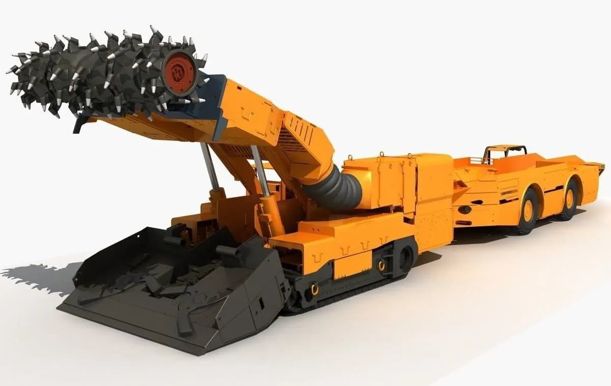
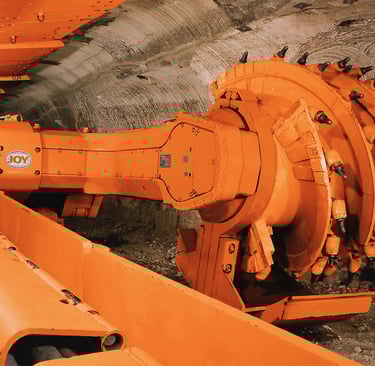
Continuous Miner: The Underground Workhorse
The continuous miner represents one of mining's most versatile pieces of equipment, earning its reputation as the backbone of room-and-pillar mining operations across Australia's coal regions. Picture a machine roughly the size of a city bus, but built like a tank and equipped with a rotating cutting head that can chew through coal seams with mechanical precision. The business end features a cylindrical drum studded with tungsten carbide cutting picks, spinning at carefully controlled speeds to fracture coal from the working face.
What makes continuous miners particularly demanding from an electrical perspective is their need for precise control across multiple systems simultaneously. The cutting head requires substantial torque to maintain consistent rotation under varying geological conditions—one moment slicing through soft coal, the next encountering harder rock bands or pyrite inclusions. The machine's conveyor system must operate in perfect synchronisation, gathering the freshly cut coal and transferring it to shuttle cars or conveyor belts for transport to the surface.
Australian miners have developed their own vernacular for these machines, reflecting both affection and respect for equipment that represents their livelihood. "The Cutter" remains the most common term, though you'll often hear miners refer to their continuous miner as "The Mule"—a reference to its stubborn reliability and ability to work long shifts without complaint. In Queensland's Bowen Basin, some crews call their machine "The Buggy," particularly when discussing transport between working sections.
The electrical demands of a continuous miner typically range from 950kW to 1500kW, requiring 3.3kV or higher voltage levels to efficiently deliver this power while maintaining reasonable cable sizes. The machine's electrical system must power not only the cutting drum but also hydraulic pumps for boom positioning, ventilation fans for dust control, lighting systems for operator visibility, and sophisticated control circuits that monitor everything from methane levels to cutting drum temperature.
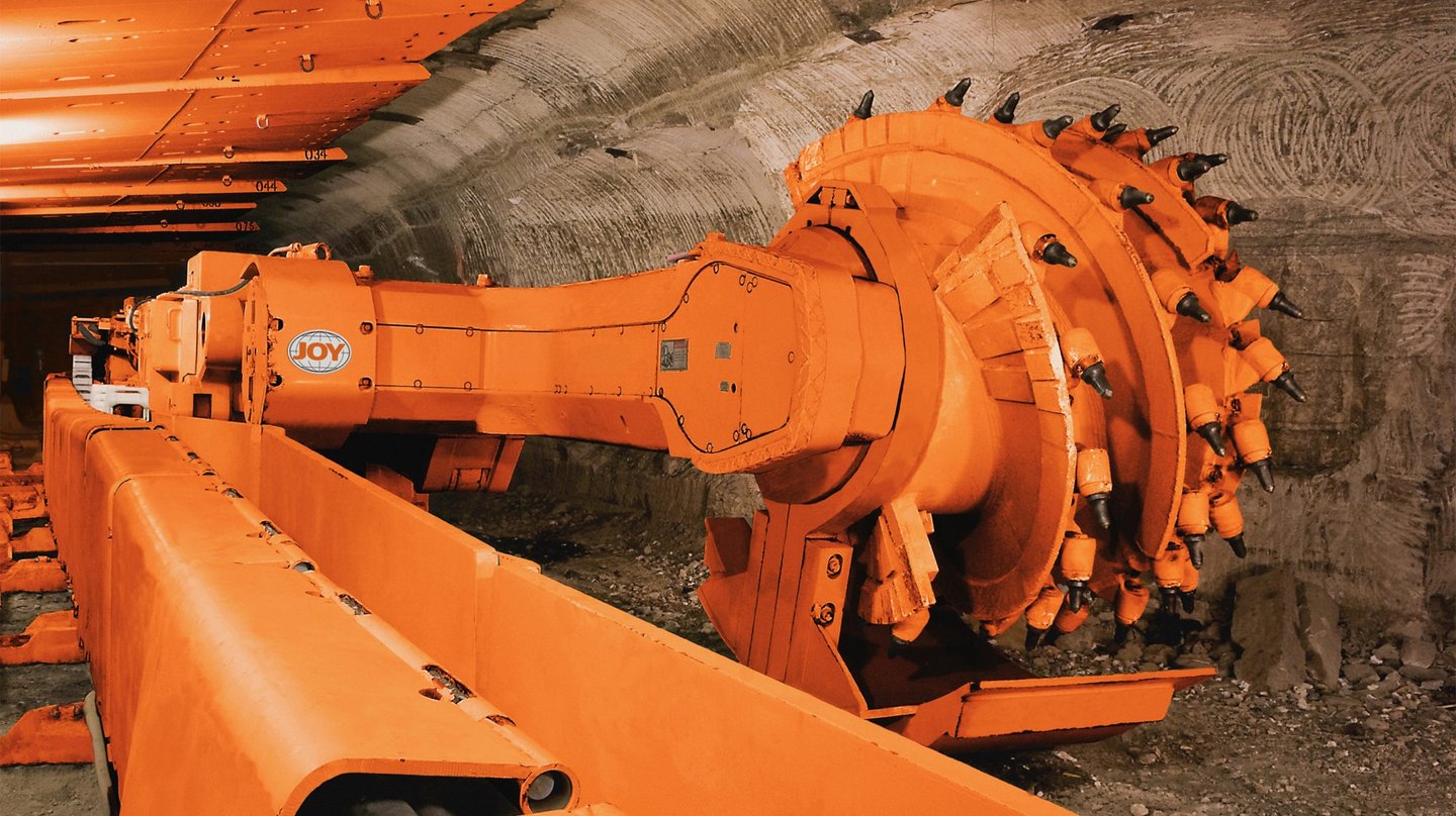
Longwall Shearer(Shearer): Automated Precision at Scale
While continuous miners excel at flexibility and selective extraction, longwall shearers represent the pinnacle of automated coal production. These machines operate along faces that can extend 300 metres or more, methodically shearing coal in passes that gradually retreat toward the main tunnels. The shearer itself resembles a massive mechanical crab, with cutting drums mounted on extendable arms that can adapt to varying seam heights and geological conditions.
The technical sophistication of modern longwall shearers demands electrical systems of extraordinary complexity. Each cutting drum requires independent speed control to optimise cutting efficiency across the face width, while the machine's traction system must maintain precise positioning along the armoured face conveyor (AFC). Hydraulic systems control drum height and cutting sequence, water pumps provide dust suppression and bit cooling, and an array of sensors monitor everything from drum wear to conveyor loading.
Underground crews have developed their own language for these machines, with "The Shearer" being the most straightforward term. However, the machine's impressive cutting capacity has earned it nicknames like "Big Bite" in New South Wales operations, while its methodical progress along the coal face has led to the moniker "Face-crawler" in some Queensland mines. The reverence in these terms reflects the machine's critical role—a single longwall shearer can produce thousands of tonnes of coal per shift when operating efficiently.
The electrical specifications for longwall shearers typically exceed those of continuous miners, often requiring 3.3kV to 11kV power systems delivering 2000kW or more. This power must be delivered through cables capable of following the shearer's continuous movement along the face, requiring exceptional flexibility combined with robust protection against the abrasive environment of the coal face.

Electrical Specifications of Type 455 Cables
Understanding the electrical characteristics of Type 455 cables requires appreciating the unique challenges of underground power distribution. Unlike surface electrical systems where cables remain stationary in controlled environments, mining cables must deliver high-voltage power while constantly flexing, stretching, and compressing as equipment moves through the workings.
The Type 455 series encompasses voltage ratings from 3.3kV up to 33kV, though the 3.3kV and 6.6kV variants see the most common application in continuous miner and shearer operations. This voltage range represents a careful balance between power delivery efficiency and safety considerations in underground environments where space constraints and explosive atmosphere regulations create unique challenges.
Compliance with Australian and New Zealand standards forms the foundation of Type 455 cable design. AS/NZS 2802:2000 specifically addresses the requirements for reeling and trailing cables in mining applications, establishing performance criteria that go far beyond conventional power cables. AS/NZS 1125 provides additional guidance on electrical installations in explosive atmospheres, while AS/NZS 3808 covers the specific requirements for underground coal mines. AS/NZS 5000.1 addresses the broader electrical safety requirements that apply to all mining electrical installations.
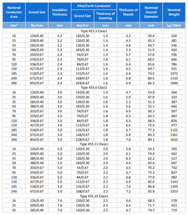
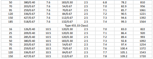
The cable designation system—455.3, 455.6, 455.11, 455.22, and 455.33—reflects the increasing insulation thickness designed to handle progressively higher voltage applications. The Type 455.3 variant, with its 2.2mm insulation thickness, serves primarily in 3.3kV applications where flexibility and weight considerations outweigh the need for maximum electrical protection. Moving up the range, the Type 455.33 features 10.5mm insulation thickness, providing the electrical integrity required for higher voltage applications but at the cost of increased cable diameter and weight.
The importance of semiconductive screens in mining cable design cannot be overstated. These conductive layers, applied directly over the conductor and beneath the outer insulation, serve to equalise electrical stress distribution around the conductor circumference. In mining applications where cables experience constant flexing and potential mechanical damage, this stress control becomes critical to preventing partial discharge phenomena that could lead to insulation failure.
EPR (Ethylene Propylene Rubber) insulation represents the current state-of-the-art for mining cable applications, offering superior resistance to ozone, heat, and mechanical stress compared to earlier PVC or XLPE formulations. The elastomeric properties of EPR allow it to maintain its insulating characteristics even when subjected to the repeated compression and extension cycles that characterise reeling and trailing applications.
Textile reinforcement provides mechanical support that prevents the cable from stretching under its own weight when suspended vertically or dragged horizontally behind moving equipment. This reinforcement must be carefully balanced—too little, and the cable may suffer mechanical failure; too much, and the cable becomes excessively stiff, creating handling difficulties and potential stress concentration points.


Structural Features of Type 455 Cable
The internal architecture of Type 455 cables reflects decades of evolution in mining cable design, with each component optimised for the specific demands of underground power distribution. Beginning at the core, the conductor construction utilises flexible, stranded, tinned copper to provide the conductivity required for high-current applications while maintaining the flexibility essential for reeling and trailing service.
The tinning process involves coating individual copper strands with a thin layer of tin, providing protection against corrosion in the humid, chemically aggressive environment typical of underground mines. This tinning also improves the conductor's resistance to oxidation during the cable manufacturing process, ensuring consistent electrical performance throughout the cable's service life. The stranding pattern follows carefully engineered specifications that balance conductivity with flexibility—too few strands, and the conductor becomes stiff and prone to fatigue failure; too many, and manufacturing costs increase while actual flexibility improvements diminish.
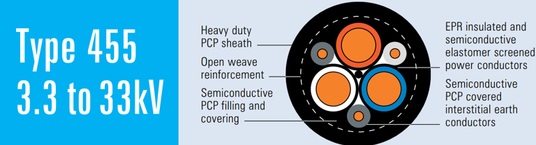
Moving outward from the conductor, the insulation system represents perhaps the most critical aspect of cable design. The EPR insulation provides the primary electrical barrier, while the semiconductive screens above and below create controlled electrical stress distribution. This three-layer system—conductor screen, EPR insulation, and insulation screen—forms what electrical engineers term a "screened cable system," providing superior electrical performance compared to unscreened alternatives.
The conductor screen, applied directly over the conductor surface, eliminates air gaps that could become sites for partial discharge activity. In mining applications where cables may experience physical damage or contamination, this screen provides the first line of defence against electrical failures. The insulation screen, positioned between the EPR insulation and the cable's outer layers, provides a smooth, conductive surface that prevents electrical stress concentrations at the insulation boundary.
Central to the cable's mechanical design is the elastomer centre filler, which maintains the cable's circular cross-section and provides mechanical support for the conductor assembly. This filler must possess sufficient flexibility to allow cable bending while providing enough structural integrity to prevent conductor displacement under mechanical stress. The material selection for this component requires balancing thermal stability, chemical resistance, and mechanical properties across the wide temperature ranges encountered in mining applications.
The interstitial earth conductors—two separate earth cores positioned in the spaces between the main conductors—provide redundant grounding paths essential for mining safety regulations. These conductors utilise CSP (Chlorosulfonated Polyethylene) covering that provides excellent resistance to oil, chemicals, and abrasion. The redundant earth system ensures that electrical protection remains effective even if one earth conductor suffers damage during service.
Equally important is the pilot conductor, which carries control and communication signals between the mining equipment and control systems. This conductor features EPR covering similar to the main insulation system, ensuring signal integrity in the electrically noisy environment of mining operations. The pilot core must maintain its electrical characteristics despite the mechanical stresses imposed by cable movement and the electromagnetic interference generated by high-power equipment.
The textile reinforcement layer provides tensile strength that prevents cable elongation under mechanical stress. This reinforcement typically consists of high-strength synthetic fibres arranged in an open-weave pattern that allows flexibility while providing mechanical support. The open-weave design prevents the creation of a moisture barrier that could trap water within the cable structure.
Finally, the extra-heavy duty PCP (Polychloroprene) sheath provides the cable's primary protection against the harsh underground environment. This outer covering must resist abrasion from rock surfaces, chemical attack from mine water and gases, flame propagation in case of fire, and mechanical damage from equipment contact. The sheath thickness varies with cable type, reflecting the balance between protection and handling characteristics required for different applications.


Installation and Handling Best Practices
Proper installation of Type 455 cables begins long before the cable reaches the underground workplace, starting with careful planning of cable routes and installation methodology. The reel-in method represents the most critical aspect of underground cable installation, requiring techniques that minimise mechanical stress while ensuring reliable electrical connections.
The fundamental principle of cable reeling involves maintaining minimal torsion throughout the installation process. Unlike surface installations where cables can be pulled through conduits or laid in trenches, underground reeling requires the cable to follow equipment movement while maintaining electrical continuity. This demands installation techniques that account for the cable's "memory"—its tendency to retain coiling characteristics from the supply reel.
Experienced mining electricians understand that successful cable installation begins with proper reel positioning. The supply reel must be positioned to allow smooth cable payout without creating twist or kinks that could compromise the cable's mechanical integrity. The phrase "Feed the snake slow" reflects the wisdom of allowing the cable to naturally assume its installed configuration rather than forcing it into position through excessive tension.
Anchoring techniques require particular attention in mining applications where equipment movement and ground settlement can create unexpected stresses on cable installations. Secure loops near junction boxes distribute mechanical stress over extended cable lengths rather than concentrating forces at connection points. These loops must be sized appropriately—too small, and the cable experiences excessive bending stress; too large, and the loops become vulnerable to damage from equipment contact.
The concept of cable memory becomes particularly important when working with larger cable sizes that retain significant coiling characteristics from their original reeling. Miners often refer to managing this memory as "convincing the cable" to follow the desired path, recognising that working with rather than against the cable's natural tendencies produces superior installations with longer service life.
Grounding procedures for Type 455 cables require meticulous attention to ensure both electrical safety and regulatory compliance. The dual earth conductor system provides redundancy, but proper connection of both earth cores remains essential. Underground grounding systems must account for the corrosive mine environment and the potential for ground movement that could compromise electrical connections.
The practical wisdom embedded in mining vernacular reflects decades of hard-won experience with cable handling. "Don't twist the pig tail" refers to the importance of maintaining proper conductor orientation during connection procedures, while "Keep the juice line happy" encompasses the full range of practices that ensure reliable power delivery to critical equipment.
Temperature considerations play a crucial role in installation planning, as underground temperature variations can cause significant cable expansion and contraction. Installations must include sufficient service loops to accommodate this thermal movement without creating mechanical stress that could lead to premature failure.
Real-World Usage & Mining Slang
The language of underground mining reflects both the practical wisdom accumulated over generations of coal extraction and the particular affection miners develop for equipment that represents their livelihood and safety. Understanding this vernacular provides insight into how Type 455 cables integrate into the daily reality of underground operations.
The term "drag tail" encompasses more than simple description of a cable following behind equipment—it represents the entire philosophy of mobile power distribution in confined underground spaces. A properly managed drag tail moves smoothly with equipment, maintains appropriate service loops, and avoids contact with roof supports or floor irregularities that could cause damage. Miners speak of a drag tail that "behaves well," reflecting the cable's ability to follow equipment movement without creating handling difficulties or electrical problems.
"Juice line" serves as the universal mining term for power cables, but the phrase carries connotations beyond simple electrical function. A reliable juice line represents the difference between productive operation and costly downtime, between meeting production targets and falling behind schedule. When miners speak of "keeping the juice flowing," they're acknowledging the critical role that cable reliability plays in successful mining operations.
The term "chock cable" refers to power cables positioned near hydraulic roof supports, highlighting one of the unique challenges of longwall mining operations. As the longwall advances and roof supports are repositioned, cables must be carefully managed to avoid damage from the massive hydraulic cylinders and structural components that comprise the roof support system. Experienced longwall crews develop specific techniques for "nursing the chock cable" through support advance cycles, ensuring electrical continuity while protecting the cable from mechanical damage.
When underground crews encounter unexpected cable damage, their response reflects both regulatory requirements and practical necessity. The immediate protocol—"kill the power, check the damage"—ensures worker safety while allowing assessment of repair requirements. Underground-rated splice kits provide temporary repair capability, but miners understand that such repairs represent short-term solutions. The phrase "patch it and plan it" reflects the dual approach of implementing immediate repairs while scheduling permanent cable replacement during planned maintenance periods.
Equipment operators develop intimate familiarity with their machines' electrical characteristics, often detecting cable problems through subtle changes in equipment behaviour long before formal electrical testing reveals issues. A continuous miner operator might notice slight changes in cutting drum performance that indicate developing cable problems, while longwall shearer operators monitor electrical parameters that provide early warning of insulation degradation or connection issues.
The collaborative nature of underground cable management appears in phrases like "help the cable help you," emphasising that proper equipment operation includes consideration of electrical system limitations. Operators learn to avoid sharp turns, excessive cable tension, and rapid acceleration or deceleration that could stress the electrical system beyond design limits.
Maintenance crews develop their own specialised vocabulary around cable inspection and testing procedures. "Megger the line" refers to insulation resistance testing using a megohmmeter, while "check the pilot" encompasses the full range of control circuit testing required to ensure proper equipment operation. These testing procedures become routine elements of shift preparation, with experienced crews capable of quickly identifying and addressing developing electrical problems before they result in equipment failures.
Common Issues & FAQ
Q1: What happens when the cable insulation gets damaged underground?
When insulation damage occurs in underground mining operations, the immediate response protocol prioritises worker safety above all other considerations. The first step involves completely de-energising the affected circuit using proper lockout/tagout procedures, ensuring that electrical energy cannot accidentally be restored during investigation and repair procedures. This step cannot be rushed or bypassed, as underground mining environments present unique electrical hazards due to the combination of moisture, metallic equipment, and confined spaces.
Following safe isolation, thorough inspection becomes essential to determine the extent and nature of the damage. Minor insulation damage might manifest as discolouration or surface abrasion, while more serious damage could involve conductor exposure or water ingress into the cable structure. The inspection process requires proper lighting and often involves cleaning the affected area to accurately assess damage severity.
Underground-rated splice kits provide the primary method for temporary repairs, but their application requires careful consideration of environmental conditions and electrical requirements. These kits typically include moisture-sealing compounds, insulating materials rated for the cable's voltage level, and mechanical protection designed to withstand the underground environment. However, miners must understand that splice repairs, while effective for maintaining short-term operation, represent temporary solutions that should be replaced with new cable sections during planned maintenance periods.
The decision between temporary repair and immediate replacement depends on factors including damage location, production requirements, and available replacement cable inventory. Critical production situations might justify temporary repairs to maintain operation until scheduled maintenance periods, while damage near junction boxes or in easily accessible locations might warrant immediate permanent repair.
Q2: Can Type 455 be used interchangeably across different machines?
The question of interchangeability reflects a common misconception that mining cables with similar voltage ratings can be freely substituted across different equipment applications. In reality, successful cable selection requires matching multiple parameters including conductor size, insulation thickness, overall diameter, weight, and flexibility characteristics to specific equipment requirements.
Continuous miners and longwall shearers present dramatically different cable requirements despite similar voltage specifications. Continuous miners typically require cables optimised for frequent coiling and reeling operations, favouring smaller diameters and enhanced flexibility even at some compromise in electrical protection. Longwall shearers, operating in more predictable geometric patterns, can accommodate larger, more robust cables that provide superior electrical protection for high-power applications.
The mechanical characteristics of reeling systems impose specific constraints on cable selection. Equipment designed for Type 455.3 cables (39.4mm diameter for 16mm² conductor) cannot accommodate Type 455.33 cables (83.0mm diameter) due to reel size limitations and increased weight. Similarly, the cable storage and handling systems integrated into mining equipment often have dimensional limitations that prevent substitution of larger cable variants.
Electrical protection systems must also be considered when evaluating cable interchangeability. Different cable types may have varying capacitance and inductance characteristics that affect protective relay operation, while insulation thickness variations can influence fault current distribution and earth fault detection sensitivity.
Q3: How to tell if the pilot or earth core is compromised?
Detecting problems with pilot or earth conductors requires systematic testing procedures that go beyond simple visual inspection. The pilot conductor carries control signals essential for equipment operation, while the earth conductors provide the safety grounding required by mining regulations. Failure of either system can compromise both equipment functionality and worker safety.
Insulation resistance testing using a megohmmeter (commonly called "meggering") provides the primary method for detecting pilot and earth conductor problems. This testing involves applying a high voltage (typically 500V or 1000V) between the conductor and earth while measuring the resulting leakage current. Healthy conductors should exhibit insulation resistance values exceeding 1 megohm per kilometre of cable length, while degraded insulation produces lower readings that indicate developing problems.
The testing procedure requires isolating the conductor from all connected equipment to prevent damage to sensitive electronic components. Control systems, variable frequency drives, and monitoring equipment must be disconnected before applying test voltages. Testing should be performed under consistent environmental conditions, as temperature and humidity can significantly affect insulation resistance readings.
Visual inspection during routine maintenance provides complementary information to electrical testing. Signs of conductor problems include discolouration of cable covering materials, moisture ingress at connection points, and physical damage to cable protective covering. The pilot conductor covering should maintain consistent colour and texture along the cable length, while earth conductor connections should show no signs of corrosion or loosening.
Continuity testing verifies that conductors maintain electrical connection throughout their length without unwanted high-resistance connections that could compromise performance. This testing uses low-voltage ohmmeters to measure conductor resistance, comparing results against manufacturer specifications that account for conductor material, cross-sectional area, and temperature.
Q4: Is thicker always better?
The relationship between cable thickness and performance involves complex tradeoffs that make "thicker is better" an oversimplification of cable selection principles. While increased insulation thickness generally provides superior electrical protection and longer service life under adverse conditions, these benefits come at the cost of increased weight, larger diameter, and reduced flexibility that can create handling and installation difficulties.
Type 455.33 cables, with their 10.5mm insulation thickness, offer maximum electrical protection against voltage surges, partial discharge, and insulation degradation. This protection becomes particularly valuable in applications where cables experience severe environmental conditions or where replacement costs and downtime penalties justify the additional investment in cable protection. However, these cables weigh significantly more than thinner alternatives—a 16mm² Type 455.33 cable weighs 822 kg per 100 metres compared to 224 kg per 100 metres for equivalent Type 455.3 cable.
The increased weight creates practical difficulties in underground installations where manual handling limitations and equipment capacity constraints become important factors. Reeling systems designed for lighter cables may lack the mechanical strength to handle heavier alternatives, while increased cable diameter can exceed the clearance limitations of underground roadways and equipment positioning systems.
Flexibility represents another crucial consideration in cable selection. Thicker insulation generally reduces cable flexibility, making installation more difficult and potentially creating stress concentration points where cables must bend around obstacles or follow equipment movement. Mining applications requiring frequent cable coiling and reeling particularly benefit from optimised flexibility that reduces mechanical stress during normal operation.
Economic factors also influence the thickness decision, as thicker cables command premium prices that must be justified through extended service life or reduced maintenance costs. Applications where cables receive good mechanical protection and operate in relatively benign environments may not justify the additional cost of maximum thickness options.
Q5: What is the lifespan of Type 455 cables in high-abrasion zones?
Cable service life in high-abrasion mining environments depends on a complex interaction of factors including mechanical protection, handling practices, environmental conditions, and maintenance procedures. The typical range of 6 to 18 months reflects the wide variation in operating conditions encountered across different mining operations and equipment applications.
High-abrasion zones typically occur where cables contact rock surfaces, equipment components, or structural supports during normal operation. Continuous miner applications often create severe abrasion conditions as cables drag across mine floors that may contain rock debris, spilled coal, and moisture that accelerates wear processes. The repeated flexing action as equipment moves between working faces creates additional mechanical stress that compounds abrasion effects.
Protective measures can significantly extend cable life in abrasion-prone applications. Cable protectors, drag chains, and mechanical guides reduce direct contact between cables and abrasive surfaces, while proper installation techniques that maintain appropriate service loops prevent excessive tension that accelerates wear. Some operations employ sacrificial wear pads or sleeves at critical wear points, replacing these protective elements more frequently than the underlying cable.
Environmental factors play crucial roles in determining cable longevity. High humidity conditions accelerate chemical degradation of cable covering materials, while acidic mine water can attack metallic components and compromise protective coatings. Temperature variations create expansion and contraction cycles that stress cable materials, while exposure to oils and hydraulic fluids can soften or swell elastomeric cable components.
Maintenance practices significantly influence cable service life through regular inspection programs that identify developing problems before they result in cable failure. Visual inspections can detect early signs of abrasion damage, allowing protective measures to be implemented before cable integrity becomes compromised. Electrical testing programs monitor insulation condition and identify degradation trends that indicate approaching end-of-service-life conditions.
The economic analysis of cable replacement involves balancing cable costs against downtime penalties and maintenance labor requirements. Operations with high production values may justify more frequent cable replacement to minimise the risk of unexpected failures, while lower-intensity operations might accept longer replacement intervals with correspondingly higher failure risk.
Proper documentation of cable performance provides valuable feedback for optimising cable selection and installation practices. Tracking service life across different cable types, installation methods, and operating conditions helps mining operations develop replacement strategies that balance cost considerations with reliability requirements.
Conclusion
The Type 455 cable series represents more than merely a technical solution to underground power distribution challenges—it embodies the accumulated wisdom of decades spent perfecting electrical systems for the world's most demanding industrial environment. These cables serve as the critical link between surface-generated electrical power and the massive machines that extract coal from seams hundreds of metres below ground, enabling the continuous operation that modern mining economics demand.
Understanding Type 455 cables requires appreciating the intricate balance of engineering compromises that define their design. Every aspect of their construction—from the molecular composition of insulation materials to the geometric arrangement of conductor strands—reflects careful optimisation for the unique demands of underground mining. The progression from Type 455.3 through Type 455.33 variants provides mining operations with options that can be precisely matched to specific applications, whether prioritising flexibility for continuous miner reeling operations or maximum electrical protection for high-voltage longwall applications.
The integration of these cables with mining equipment extends far beyond simple electrical connections. Successful underground operations require intimate understanding of how cable characteristics influence equipment performance, how installation practices affect service life, and how maintenance procedures can maximise reliability while minimising operational disruption. The vernacular that miners have developed around cable management reflects this deep understanding, encoding practical wisdom that cannot be captured in technical specifications or installation manuals.
As mining technology continues evolving toward greater automation and higher power densities, the demands placed on electrical distribution systems will only intensify. Continuous miners are becoming more sophisticated, with advanced control systems that require reliable communication links alongside power distribution. Longwall shearers are growing larger and more capable, demanding higher power levels delivered through increasingly complex electrical systems. Future cable developments must accommodate these trends while maintaining the reliability and durability that underground mining operations require.
The economic implications of cable selection and management extend throughout mining operations, influencing everything from production schedules to maintenance budgets. Proper cable specification can mean the difference between smooth operations that consistently meet production targets and problematic installations that require frequent intervention and create operational uncertainty. The investment required for premium cable solutions must be evaluated against the potential costs of premature failure, including lost production, emergency repair expenses, and safety risks associated with unexpected electrical problems.
Looking toward the future, Type 455 cables and their successors will play increasingly critical roles in enabling the transition toward more sustainable and efficient mining operations. As the industry embraces electrification as a pathway to reduced emissions and improved worker health, the reliable delivery of electrical power becomes even more fundamental to successful mining operations. The cables that power today's continuous miners and longwall shearers are laying the foundation for tomorrow's fully automated, electrically powered mining systems.
The story of Type 455 cables ultimately reflects the broader narrative of industrial innovation—the patient process of identifying real-world challenges, developing technical solutions, and refining those solutions through practical experience. In the depths of underground mines where these cables serve, engineering theory meets operational reality, and successful solutions emerge from the synthesis of technical knowledge and practical wisdom. As mining operations continue pushing the boundaries of what's possible in underground extraction, robust and reliable cables like the Type 455 series remain the essential lifelines that make it all possible.

