Underground Mining Cables: A Comprehensive Guide to AS/NZS 1972:2006 Type 2S 1.1/1.1 kV & 3.3/3.3 kV Individually Screened Cables in Australian Mining Operations
Discover AS/NZS 1972:2006 Type 2S mining cables for Australian underground mines. Learn about 1.1kV and 3.3kV individually screened cables, applications, electrical specifications, and solutions to common mining challenges.
7/1/202514 min read
AS/NZS 1972:2006 Type 2S 1.1/1.1 kV & 3.3/3.3 kV Individually Screened underground Mining Cables
Introduction: The Foundation of Underground Mining Safety
In the depths of Australia's underground mines, where temperatures soar, moisture levels fluctuate dramatically, and mechanical stresses are constant, the electrical infrastructure must be absolutely reliable. The AS/NZS 1972:2006 standard represents the backbone of electrical safety in Australian underground mining operations, specifically addressing the critical requirements for fixed cables used in coal mines and other underground environments.
Think of these cables as the nervous system of a mine - they carry not just electrical power, but also the vital control signals that keep miners safe and operations running smoothly. The Type 2S individually screened cables we're exploring today are specifically engineered to handle the harsh realities of underground mining while maintaining the highest standards of electromagnetic compatibility (EMC) and electrical safety.
The importance of proper cable selection cannot be overstated. When you're operating hundreds of metres below ground, with limited access for repairs and maintenance, every component must be built to withstand conditions that would destroy ordinary electrical equipment. These cables serve as the lifeline connecting surface operations to underground machinery, lighting systems, and critical safety equipment.
Australia's Underground Mining Landscape: Where These Cables Make Their Mark
Australia's underground mining industry represents some of the most challenging environments on Earth, and understanding these locations helps us appreciate why specialised cables like the Type 2S are essential. Let's take a journey through the major underground mining regions where these cables prove their worth daily.
In Western Australia, the legendary Kalgoorlie region, home to the famous Super Pit, extends deep underground through a network of mines that have been operating for over a century. The Kalgoorlie Consolidated Gold Mines (KCGM) operations require extensive underground electrical infrastructure to power ventilation systems, hoisting equipment, and processing machinery. The extreme temperatures and rock dust in these gold mines create an environment where only the most robust cables can survive.
The Boddington Gold Mine, also in Western Australia, represents one of the largest gold mines in Australia and requires sophisticated electrical systems for its underground operations. Here, Type 2S cables manage the power distribution for massive crushing equipment and conveyor systems that operate continuously in challenging conditions.
Moving to New South Wales, the Cadia-Ridgeway operations showcase how modern underground mining relies on advanced electrical infrastructure. These mines require precise control systems for their automated equipment, making the individually screened design of Type 2S cables crucial for preventing electromagnetic interference that could disrupt operations.
The St Ives Gold Mining Company operations in Western Australia demonstrate another critical application area. Their underground mines require flexible, durable cables that can withstand the constant movement and vibration associated with mobile mining equipment while maintaining reliable electrical connections.
In Queensland, the story shifts to coal mining, where the Bowen Basin hosts numerous underground operations including Moranbah North, Kestrel, and other significant mines. These coal mining environments present unique challenges including the presence of methane gas, coal dust, and the need for explosion-proof electrical systems. The Type 2S cables used here must meet stringent safety requirements while providing reliable power to longwall mining equipment and ventilation systems.
South Australia contributes the remarkable Olympic Dam mine, a polymetallic operation extracting copper, uranium, gold, and silver. This mine's diverse mineral extraction processes require different types of electrical systems, from high-power grinding circuits to precise control systems for chemical processing equipment.
The Cannington mine in Queensland, known as one of the world's largest silver-lead-zinc mines, operates sophisticated underground systems requiring both power and control cables. The individually screened design of Type 2S cables becomes crucial here, where sensitive measurement equipment must operate alongside high-power mining machinery without interference.
Application Scenarios: Where Type 2S Cables Excel Underground
Understanding how Type 2S cables are actually used in underground mining helps us appreciate their sophisticated design. These cables serve multiple critical functions, each requiring specific electrical and mechanical characteristics.
The primary application involves powering fixed machinery installations throughout underground mine networks. Think of the massive ventilation fans that ensure breathable air reaches working areas, or the crushing equipment that processes ore before it travels to the surface. These machines operate continuously under extreme conditions, requiring cables that can deliver consistent power without failure. The individual screening on each conductor becomes essential here because electromagnetic interference from one high-power machine could disrupt the operation of sensitive control systems on another.
Mobile equipment represents another crucial application area. Underground mining vehicles, from personnel carriers to massive ore haulers, require flexible power connections that can withstand constant movement, vibration, and the occasional impact from falling rock. The Type 2S design incorporates elastomer centre fillers and heavy-duty CPE sheathing specifically to handle these mechanical stresses while maintaining electrical integrity.
Longwall lighting circuits present unique challenges that showcase why individually screened cables are necessary. In longwall mining operations, lighting systems must operate reliably in areas where coal cutting machinery generates significant electromagnetic interference. The individual screening on each conductor prevents this interference from causing lighting failures that could compromise worker safety. Additionally, these lighting circuits often include pilot and control cores that manage automated switching and emergency lighting systems.
Control and communication systems represent perhaps the most critical application for Type 2S cables. Modern underground mines rely heavily on automated systems for monitoring air quality, controlling ventilation, managing conveyor systems, and maintaining communication with surface operations. These systems use twisted-pair and screened cores within the same cable that carries main power circuits. The individual screening prevents power conductors from interfering with sensitive control signals, ensuring that safety systems can operate reliably even when high-power equipment is running nearby.
Emergency systems integration showcases another vital application. Underground mines must maintain reliable communication and lighting systems that can operate during power outages or other emergencies. Type 2S cables often carry both main power circuits and backup power systems within the same cable assembly, with individual screening ensuring that emergency systems remain functional even if main power circuits experience problems.
Standards and Construction: Engineering Excellence Underground
The AS/NZS 1972:2006 standard represents decades of engineering experience and safety considerations specific to underground mining environments. This standard, which was reconfirmed in 2020, works in conjunction with AS/NZS 1125 and AS/NZS 3808 to provide comprehensive guidelines for underground electrical installations.
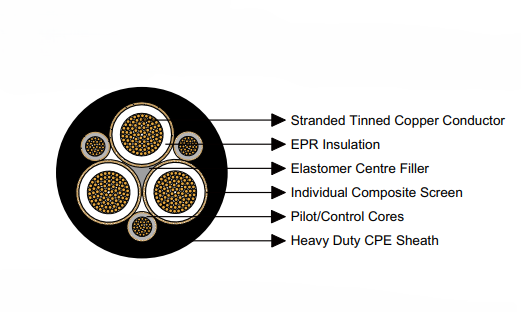
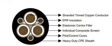
Understanding the construction of Type 2S cables reveals why they perform so well in challenging underground conditions. The foundation begins with stranded tinned annealed copper conductors. The stranding provides flexibility essential for cable installation in confined spaces, while the tinning prevents corrosion in the humid, sometimes acidic conditions found underground. The annealed copper ensures maximum conductivity, critical when cables must carry power over long distances through mine workings.
The insulation system uses EPR (Ethylene Propylene Rubber), chosen specifically for its performance in underground environments. EPR maintains its electrical properties across wide temperature ranges, resists chemical attack from mining chemicals and groundwater, and provides excellent mechanical properties under stress. The insulation thickness varies with voltage rating - approximately 1.2 millimetres for 1.1 kV applications and 3.0 millimetres for 3.3 kV systems, providing appropriate electrical safety margins for each voltage class.
The elastomer centre filler serves multiple critical functions. It maintains the cable's round cross-section under mechanical stress, prevents moisture ingress between conductors, and provides cushioning that protects individual conductors from damage during installation and operation. This seemingly simple component actually represents sophisticated materials engineering designed specifically for underground mining conditions.
Pilot and control cores within Type 2S cables demonstrate advanced cable design thinking. These smaller conductors, typically constructed with 30 strands of 0.20 to 0.25 millimetre copper wire, carry control signals and pilot functions. Each pilot core receives its own EPR insulation and composite screening, ensuring signal integrity even when installed alongside high-power main conductors.
The individual composite screening system represents the most sophisticated aspect of Type 2S cable construction. Each conductor receives its own screen consisting of tinned annealed copper braiding interwoven with polyester yarn. This composite construction provides both electrical screening and mechanical protection. The copper braiding creates a Faraday cage around each conductor, preventing electromagnetic interference, while the polyester yarn adds tensile strength and abrasion resistance.
The heavy-duty CPE (Chlorinated Polyethylene) sheath provides the final layer of protection. CPE was specifically chosen for mining applications because of its excellent resistance to oils, chemicals, abrasion, and flame. The sheath thickness varies with cable size and application, providing appropriate mechanical protection while maintaining flexibility for installation.
Electrical and Physical Specifications: The Technical Foundation
The electrical specifications of Type 2S cables reflect careful engineering to meet the specific demands of underground mining operations. Understanding these specifications helps explain why these cables perform reliably in challenging conditions.
Voltage ratings of 1.1/1.1 kV and 3.3/3.3 kV serve different functions in underground mining electrical systems. The 1.1 kV rating typically handles local machine circuits, lighting systems, and equipment that operates relatively close to electrical distribution points. These applications benefit from the smaller cable dimensions and increased flexibility that comes with lower voltage insulation requirements.
The 3.3 kV rating addresses higher power applications and longer cable runs common in underground mining. When electrical power must travel hundreds of metres through mine workings, higher voltage reduces current requirements, allowing smaller conductors for the same power transmission. This becomes particularly important in confined underground spaces where cable installation space is limited.
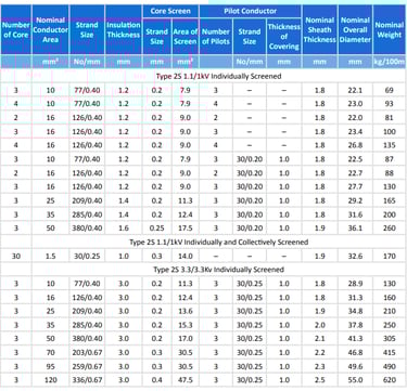
Conductor sizes ranging from 10 mm² to 120 mm² provide flexibility for different power requirements. Smaller conductors handle control circuits, lighting, and low-power equipment, while larger conductors manage high-power applications like ventilation fans, crushing equipment, and main distribution circuits. The availability of individually screened conductors up to 95 mm² in 3.3 kV applications, with unscreened options available for 120 mm² conductors, reflects practical considerations about screening effectiveness and cable manufacturing constraints.
The strand configurations reveal sophisticated conductor design. For example, 10 mm² conductors use 77 strands of 0.40 mm wire, providing excellent flexibility while maintaining good current-carrying capacity. Larger conductors like 70 mm² use 203 strands of 0.67 mm wire, balancing flexibility with the mechanical strength needed to support the conductor's weight during installation.
Insulation thickness specifications directly relate to electrical safety and performance. The 1.2 mm insulation on 1.1 kV cables provides appropriate dielectric strength with a substantial safety margin, while the 3.0 mm insulation on 3.3 kV cables ensures reliable performance even under the mechanical stress and environmental conditions found underground.
Screen specifications demonstrate the sophisticated electromagnetic compatibility design. Screen areas ranging from 7.9 mm² for small conductors to 47.5 mm² for large conductors ensure effective screening while providing adequate current-carrying capacity for fault currents and normal screen currents.
Physical dimensions reveal the practical considerations of underground cable installation. Overall diameters ranging from 22.1 mm to 55.0 mm must fit through cable entry points on mining equipment while providing adequate conductor and insulation cross-sections. Cable weights from 69 kg/100m to 620 kg/100m affect installation methods and support requirements in underground applications.

Underground Mine Environments: Understanding the Operational Challenges
Underground mining environments present unique challenges that ordinary electrical cables simply cannot withstand. Understanding these conditions helps explain why Type 2S individually screened cables incorporate such sophisticated design features.
Mechanical stresses in underground mines far exceed those found in typical industrial applications. Cables may be suspended from roof supports over spans of 50 metres or more, creating tensile loads that would destroy ordinary cables. Rock falls, equipment impacts, and the constant vibration from heavy machinery subject cables to mechanical stresses that require robust construction and protective measures.
Temperature variations present another significant challenge. Underground temperatures can range from near-freezing in some areas to over 60°C in deep, poorly ventilated sections. These temperature swings cause expansion and contraction that can stress cable components, particularly at termination points. The EPR insulation and CPE sheathing used in Type 2S cables maintain their properties across these temperature ranges, ensuring reliable operation.
Moisture and chemical exposure create corrosive conditions that attack ordinary electrical components. Groundwater seepage, condensation from temperature changes, and chemical solutions used in mining processes can penetrate cable systems and cause failures. The composite screening and heavy-duty sheathing of Type 2S cables provide multiple barriers against moisture ingress, while the tinned copper conductors resist corrosion even if moisture does penetrate the cable.
Electromagnetic interference (EMI) in underground mines comes from multiple sources. Variable frequency drives controlling large motors, switching operations, radio communication systems, and electronic control equipment all generate electromagnetic fields that can interfere with sensitive control circuits. The individual screening on Type 2S cables creates effective shielding around each conductor, preventing interference between power and control circuits within the same cable.
Confined spaces and limited access for maintenance make cable reliability critical. Unlike surface installations where cables can be easily replaced, underground cables may be installed in locations that are difficult or dangerous to access for repairs. The robust construction of Type 2S cables minimises the likelihood of failures that would require underground repair work.
The need for flexibility during installation cannot be overstated. Underground cable routes often involve tight bends around structural supports, threading through narrow openings, and routing around existing equipment. The elastomer centre filler and composite screening design of Type 2S cables maintain flexibility while providing necessary mechanical protection.
Frequently Asked Questions: Solving Common Underground Cable Challenges
Underground mining operations face recurring cable-related challenges, and understanding these issues and their solutions helps ensure reliable electrical systems. Let's explore the most common concerns and their practical solutions.
What causes cable sheath cracking in underground mining applications, and how can it be prevented?
Cable sheath cracking typically results from a combination of mechanical abrasion and chemical exposure unique to underground environments. Rock dust acts like sandpaper on cable sheaths, particularly where cables contact rough surfaces or experience movement during mining operations. Temperature cycling also contributes to sheath degradation, as the CPE material expands and contracts with temperature changes.
The primary solution involves implementing proper cable protection systems. Installing protective chutes or covers where cables contact abrasive surfaces significantly extends cable life. Regular inspection schedules help identify early signs of sheath damage before failures occur. When installing new cables, routing them away from high-abrasion areas and providing adequate support to prevent excessive movement reduces mechanical stress on the sheath.
How can electrical interference with control signals be prevented in underground mining operations?
Electromagnetic interference represents one of the most challenging aspects of underground electrical system design. Large motors, variable frequency drives, and switching equipment generate electromagnetic fields that can disrupt sensitive control circuits, potentially affecting safety systems and operational equipment.
The individual screening design of Type 2S cables provides the primary solution to EMI problems. Each conductor receives its own composite screen that creates a Faraday cage around the conductor, preventing external electromagnetic fields from inducing voltages in control circuits. Proper earthing of these screens is crucial - the screens must be connected to a reliable earth system at both ends of the cable run to be effective.
Additionally, correct cable installation practices help minimise EMI issues. Separating power and control circuits where possible, using twisted-pair configurations for sensitive control signals, and ensuring proper termination techniques all contribute to electromagnetic compatibility. Regular testing of screen continuity and earth connections helps maintain EMI protection over time.
What risks does moisture ingress pose to EPR insulation, and how can these risks be mitigated?
Moisture ingress poses significant risks to underground cable systems, potentially causing insulation breakdown, earth faults, and equipment damage. EPR insulation, while resistant to moisture absorption, can still experience reduced dielectric strength when exposed to water, particularly if the water contains dissolved minerals or chemicals common in mining environments.
Prevention begins with proper cable termination techniques. All cable entry points must use appropriate sealed glands designed for the specific cable type and environmental conditions. These glands must be properly installed and maintained to prevent water ingress at termination points, which represent the most common failure locations.
Regular insulation resistance testing provides early warning of moisture-related problems. Testing should be performed between conductors and between conductors and earth, with results compared to baseline measurements taken when the system was new. Declining insulation resistance values indicate moisture ingress or other insulation deterioration.
Emergency response procedures should include isolation methods for circuits showing signs of moisture-related insulation problems, and temporary solutions for maintaining critical circuits while permanent repairs are implemented.
What considerations apply when cables are suspended beneath belt conveyors or other mining equipment?
Suspended cable installations present unique mechanical and safety challenges in underground mining operations. The weight of long cable runs creates tensile stress that can damage conductors or cause failures at support points. Vibration from nearby equipment adds dynamic loading that can accelerate cable fatigue.
AS/NZS 1972:2006 Appendix D provides specific guidelines for calculating safe suspended lengths based on cable weight, conductor size, and mechanical properties. These calculations must account for the additional weight of accumulated dust or moisture on suspended cables. Support spacing should be designed to limit sag and prevent contact with moving equipment.
Abrasion protection becomes critical for suspended installations. Cable chutes or protective covers should be installed where cables might contact moving equipment or structural elements. Regular inspection of support systems and cable condition helps identify problems before failures occur.
How can pilot cores be protected from voltage surges and electrical stress?
Pilot and control cores within Type 2S cables operate at low voltages but can be damaged by voltage surges induced by switching operations, lightning, or faults in main power circuits. These small conductors are particularly vulnerable because their insulation is designed for low-voltage operation.
Surge protection devices should be installed at both ends of pilot core circuits, with ratings appropriate for the expected surge levels in underground mining environments. These devices must be coordinated with the protection systems for main power circuits to ensure proper operation during fault conditions.
The individual screening around pilot cores provides some protection against induced voltages from adjacent power conductors, but proper earthing of these screens is essential for effectiveness. Screen earth connections must be designed to carry fault currents without damage to pilot core insulation.
Regular testing of pilot core insulation helps identify degradation before failures occur. This testing should include insulation resistance measurements and, where appropriate, high-voltage testing to verify insulation integrity.
When should 3.3 kV cables be chosen over 1.1 kV alternatives?
The choice between 1.1 kV and 3.3 kV cable systems depends on several factors including power requirements, cable run length, and system design considerations. Understanding these factors helps ensure optimal system performance and cost-effectiveness.
Higher voltage systems become advantageous for long cable runs because voltage drop is proportional to current, and higher voltage allows lower current for the same power. In underground mining, where cable runs may extend hundreds of metres from distribution points to equipment locations, the lower current requirements of 3.3 kV systems can allow smaller conductor sizes, reducing cable cost and installation difficulty.
Main feeder circuits supplying multiple pieces of equipment typically benefit from 3.3 kV systems, while individual machine circuits may be more economically served by 1.1 kV systems. The higher insulation requirements of 3.3 kV cables result in larger overall cable dimensions, which may be a consideration in confined underground spaces.
System protection and switchgear costs also factor into voltage selection decisions. While 3.3 kV switchgear is generally more expensive than 1.1 kV alternatives, the reduced current requirements may allow smaller, less expensive protection devices.
Conclusion: Building Reliable Underground Electrical Infrastructure
The Type 2S individually screened cables conforming to AS/NZS 1972:2006 represent more than just electrical components - they embody decades of engineering experience and safety considerations specific to Australian underground mining operations. These cables serve as the critical link between surface electrical systems and underground equipment that keeps mines operating safely and efficiently.
Throughout Australia's diverse underground mining operations, from the gold mines of Western Australia to the coal mines of Queensland, these cables face extreme conditions that would destroy ordinary electrical systems. The sophisticated construction incorporating individual screening, robust insulation systems, and heavy-duty protective sheathing ensures reliable operation in environments characterised by mechanical stress, chemical exposure, electromagnetic interference, and limited accessibility for maintenance.
The electrical specifications of both 1.1/1.1 kV and 3.3/3.3 kV variants provide flexibility for different mining applications, from local equipment circuits to main distribution feeders. The availability of pilot and control cores within power cables streamlines installation while maintaining signal integrity through individual screening design.
Understanding the common challenges faced by underground mining cables and their solutions emphasises the importance of proper cable selection, installation, and maintenance practices. From preventing sheath cracking through protective measures to maintaining electromagnetic compatibility through proper screening and earthing, successful underground electrical systems require attention to details that might seem minor in less demanding applications.
The ongoing reconfirmation of AS/NZS 1972:2006 and its integration with related standards demonstrates the mining industry's commitment to electrical safety and reliability. As underground mining operations become deeper and more complex, the role of sophisticated cable systems like Type 2S individually screened cables becomes increasingly critical.
For mining engineers, electrical contractors, and safety professionals working in underground environments, these cables represent proven technology that addresses the unique challenges of subterranean operations. By understanding their construction, specifications, and proper application, mining operations can maintain the reliable electrical infrastructure essential for safe and productive underground mining.
The investment in quality cable systems like Type 2S individually screened cables pays dividends through reduced downtime, improved safety, and lower maintenance costs over the life of mining operations. As Australia's underground mining industry continues to evolve, these cables will remain essential components ensuring that electrical power and control systems operate reliably in some of the most challenging environments on Earth.
